Wenzhou Prance Hydraulic Equipment Co., Ltd

Pump Unloading Valve vs Relief Valve: Standby Flow and Heat
A hydraulic pump unloading valve and a relief valve can both return oil to tank, but they handle standby differently. A relief valve limits pressure by passing flow once its pressure threshold is reached. An unloading arrangement gives a running fixed-displacement pump a low-pressure return path when its flow is unnecessary. The practical question is therefore not simply which valve opens. It is how much flow crosses which pressure drop while the machine waits, how the circuit returns to work, and what still protects the system against excessive pressure.
For a machine with long idle periods, an unloading arrangement can substantially reduce hydraulic heat generation. It does not eliminate pump friction, return-line resistance, or the need for a correctly engineered protective circuit. This guide focuses on fixed-pump standby operation, rather than variable-pump compensation or a general cooler-sizing calculation.
Follow the oil during the actual standby state
Start with the machine’s circuit drawing and a defined operating state. A fixed-displacement pump driven at constant speed continues to deliver approximately the same displacement-based flow, with actual delivery affected by speed, viscosity and internal leakage. If that flow cannot enter an actuator, it must have an acceptable return route. A closed-centre directional valve does not make a fixed pump stop delivering oil.
When the only available route is the main relief valve, pressure rises until that valve passes the required flow. The pump then maintains substantial pressure while doing no useful actuator work. Energy crossing the pressure drop becomes heat. A large reservoir may slow the temperature increase, but it does not remove the continuous source of loss.
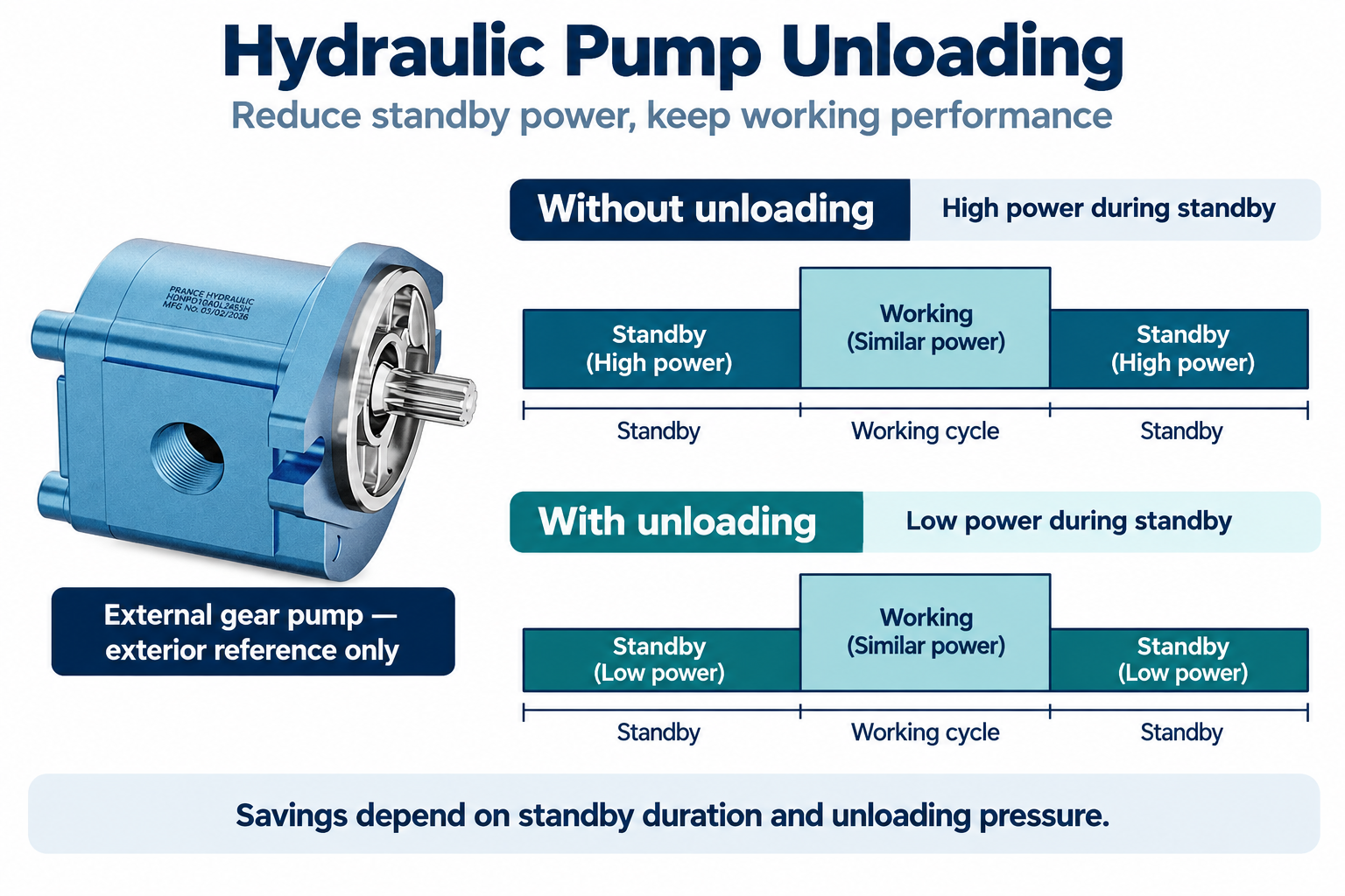
An unloading path changes that standby condition. Depending on the design, an external pilot, electrical command, or another control arrangement holds a bypass open so pump flow can return with a much smaller pressure difference. The oil still flows. The reduced pressure demand is what reduces hydraulic power consumed during the waiting period.
Compare functions before comparing valve names
The following comparison describes functions, not universal port layouts. Combined unloading-relief assemblies exist, and a valve family name alone cannot establish how a particular circuit behaves. Check the complete symbol, pilot arrangement and manufacturer’s instructions.
| Decision | Relief function | Unloading function | What to verify |
|---|---|---|---|
| Main purpose | Limit excessive pressure | Reduce pump loading when flow is unnecessary | The actual duty and control signal |
| Standby flow | May pass full flow at substantial pressure | Intended to pass pump flow at low pressure | Measured pressure drop at full standby flow |
| Control basis | Pressure acting against a setting mechanism | Pilot or command maintains the unloaded state | Pilot source, drain arrangement and reset logic |
| Return to work | Flow divides according to load and valve behaviour | Bypass must close when demand returns | Response time and transition pressure |
| Protection | Provides its specified pressure-limiting function | Does not automatically provide every protective function | Independent protection for every isolated volume |
| Energy consequence | High pressure and flow can create substantial loss | Lower standby pressure reduces hydraulic loss | Duty-weighted measurements at equal temperature |
NPTEL’s educational material distinguishes the pressure-limiting role of a relief valve from the low-load pump operation enabled by an unloading valve. That functional distinction is the basis of this table. Do not infer a safety rating or a certified circuit arrangement from this general comparison.
Calculate the loss across the return path
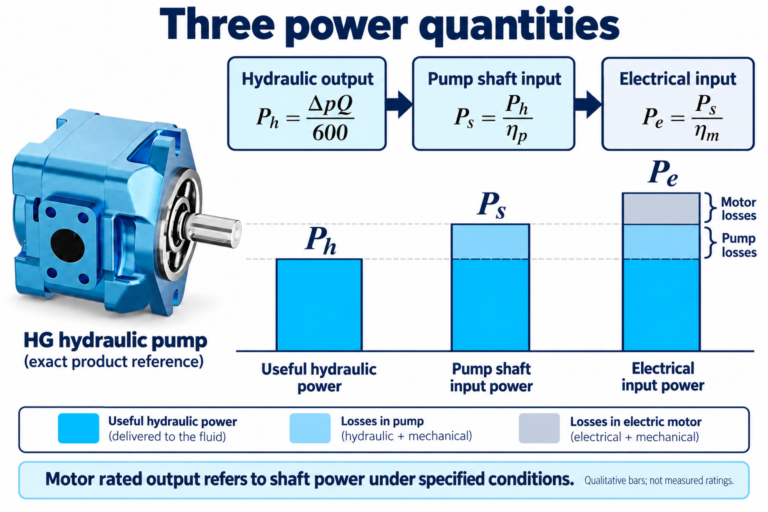
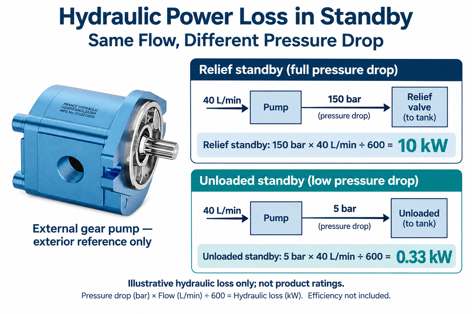
Use pressure difference across the relevant restriction, rather than a gauge reading from an unrelated branch. For oil flow expressed in litres per minute and pressure difference in bar, hydraulic power in kilowatts is pressure difference multiplied by flow, divided by 600. The conversion follows from pressure times volumetric flow in consistent SI units.
Consider an illustrative fixed pump returning 40 L/min during standby. If the pressure difference across its relief return path is 150 bar, hydraulic power dissipated across that path is 150 × 40 ÷ 600 = 10 kW. If an engineered unloading arrangement reduces the total relevant standby pressure difference to 5 bar at the same flow, the corresponding hydraulic loss is 5 × 40 ÷ 600, approximately 0.33 kW.
These figures are a calculation example, not operating limits for the illustrated Prance pump. They also exclude pump mechanical losses and electric motor losses. A purchase decision needs the real flow and pressure measured at the intended speed, oil condition and circuit arrangement. The relevant comparison is between equivalent machine states, not unrelated nameplate values.
Do not divide this valve-loss calculation by pump efficiency and call the result valve heat. Efficiency is needed when moving from hydraulic output to required shaft input. Keeping those boundaries separate avoids double-counting losses in a later thermal assessment.
Include standby duration in the energy comparison
A low unloading pressure matters most when the machine spends meaningful time waiting with the pump running. Record a complete representative cycle, including startup, approach, working stroke, holding, return and idle. A short production demonstration may hide lengthy waiting periods between batches.
For illustration, the difference between 10 kW and 0.33 kW is about 9.67 kW during the specified standby condition. If that exact condition occupies half an hour in a one-hour period, the difference in hydraulic energy is approximately 4.83 kWh. That is not a prediction of electrical savings: shaft friction, motor efficiency, control power and the rest of the duty remain outside the calculation.
Measure electrical input separately if the business case depends on electricity cost. Compare equivalent production output and oil temperature. A system that appears more economical because it completes fewer working cycles has not demonstrated an efficiency improvement at the required production rate.
Make sure the unloaded state can persist
A common design mistake is assuming that a pressure signal will remain available after the pump outlet has been unloaded. If the control needs pressure to hold the bypass open, inspect where that pressure comes from. A pilot connected to a point that collapses immediately may cause repeated opening and closing rather than stable standby operation.
Accumulator charging arrangements illustrate why pilot location matters: some circuits isolate stored pressure from the unloaded pump using a check valve and sense pressure on the stored-energy side. This is a separate design case requiring the correct unloading and recharging differential, accumulator protection and maintenance provisions. Do not add an accumulator simply to imitate a diagram.
For an electrically commanded bypass, document the permitted machine states and the behaviour on power loss. A normally open or normally closed description has consequences for startup, unexpected motion and pressure availability. The correct choice depends on the machine risk assessment and component instructions, not a universal rule that one fail state is always safer.
Coordinate the return to useful work
Reducing standby pressure is only useful if the machine can resume work correctly. When a demand command arrives, the unloading path must close in a controlled sequence so that useful flow and pressure reach the intended actuator. Examine pressure rise, actuator movement and electrical commands together.
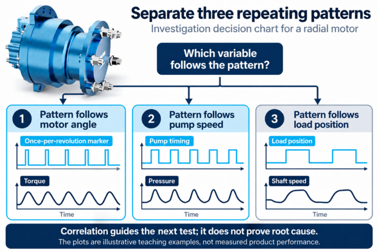
A slow transition can create delayed motion or an inability to reach the required working pressure. An abrupt transition can create a pressure transient. Neither symptom should be treated by raising a relief setting without understanding the cause. Pilot volume, drain resistance, control timing and valve dynamics can all affect the transition.
Test cold and warm oil where the approved commissioning procedure requires it. Record the actual temperature and speed rather than labelling a test merely cold or hot. Confirm repeatability over several cycles and inspect the load condition that produces the most demanding transition.
Keep pressure protection separate from energy control
An unloading command is not a substitute for verified pressure protection. Check what happens if the unloading path remains shut, a control wire fails, a pilot passage is blocked, or a directional valve isolates part of the circuit. A relief valve at the pump cannot necessarily protect every trapped volume elsewhere in the machine.
Likewise, low pump outlet pressure does not prove the whole system is depressurised. Accumulators, raised loads, trapped actuator chambers and thermal expansion can preserve or create hazardous pressure. Before maintenance, use the machine’s isolation procedure, support loads and verify the release of stored energy at the required points. NIOSH guidance on hazardous energy supports this maintenance distinction.
Never adjust a valve while relying on this article as a commissioning procedure. The responsible designer must establish settings, pressure limits and test equipment appropriate to the complete machine and its components.
Diagnose high standby temperature with matched measurements
If a supposedly unloaded system still runs hot, first establish that it is truly in its intended standby state. Check command status and the pressure difference from pump outlet to reservoir. A restrictive return filter, undersized return line or partly open bypass can leave appreciable loss even when the main relief is closed.
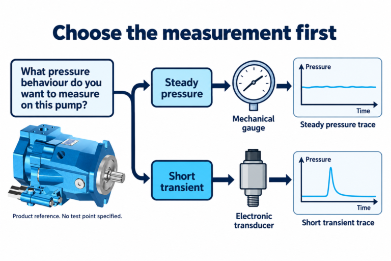
Next establish actual flow. A pressure gauge alone cannot quantify the heat generated by a return path. Compare measured flow with expected delivery at the recorded pump speed and condition. Avoid interpreting a single reduced flow reading as proof of successful unloading: internal leakage or an unintended restriction can reduce useful delivery for entirely different reasons.
Finally, separate standby losses from working-cycle losses. A machine may unload correctly between cycles and still overheat because of throttling during motion, internal leakage under load, or insufficient cooling for the real duty. Use a thermal balance only after identifying which operating phases produce the heat.
Prepare a useful pump and circuit enquiry
For an external gear pump enquiry, provide the full model identification, mounting interface, shaft arrangement, rotation, displacement requirement, operating speed and fluid conditions. Add the intended working and standby states, measured flow, pressure locations, cycle timing and the proposed control arrangement.
The Prance External Gear Pump HDH page is a product starting point. The exterior reference in the illustrations identifies the relevant pump family; it does not establish that an unloading valve is supplied, that a particular pilot arrangement is available, or that the example pressures are acceptable for an ordered model. Request a configuration-specific drawing and documented limits.
Frequently asked questions
Does an unloading valve stop a fixed-displacement pump from producing flow?
Usually the pump continues delivering flow while running. Unloading provides a lower-pressure route for that flow when useful delivery is unnecessary. Stopping the prime mover or changing pump displacement is a different control strategy.
Can a relief valve be used for continuous standby?
Only within its documented application and thermal limits, but full flow across substantial pressure creates hydraulic loss. A circuit review should assess whether an unloading arrangement, different centre condition or another approved strategy better fits the duty.
Does unloading mean zero pressure and zero heat?
No. Return-path resistance requires pressure, and pump and drive losses remain. Measure standby pressure difference and flow rather than assuming that an open bypass removes every loss.
Why does an unloading circuit keep switching between loaded and unloaded states?
Possible causes include unsuitable pilot location, pressure differential, leakage or control timing. Record pilot pressure, pump pressure and commands together before changing settings. The correct diagnosis depends on the actual valve design.
Can I remove the main relief valve after adding an unloading valve?
Do not remove pressure protection based on the presence of an unloading function. The complete circuit needs verified protection under normal operation and credible faults, including isolated volumes and stored energy.
Product and related engineering resources
External Gear Pump HDH, hydraulic pump range, variable-pump pressure compensation, whole-system heat generation, pump-drive electric motor sizing.
Technical and safety references
- NPTEL: pressure relief valve principles
- NPTEL: unloading valve operation
- NIOSH: preventing injury from hazardous energy
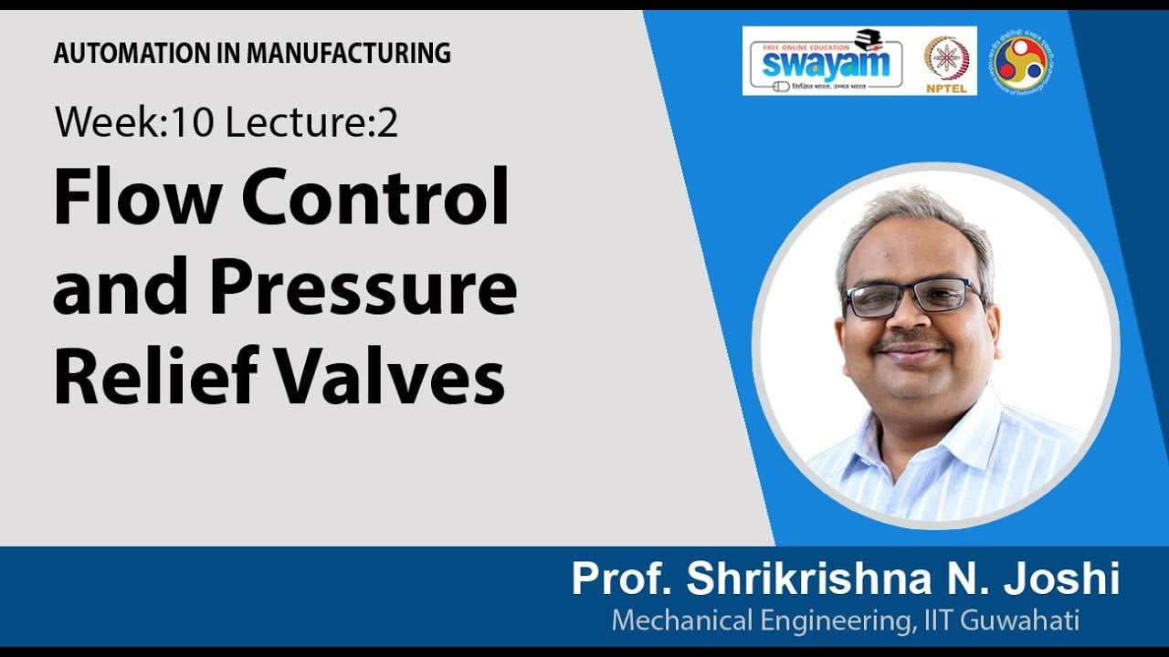
University lesson: pressure relief and flow control
NPTEL IIT Guwahati presents Dr. Shrikrishna N. Joshi’s Automation in Manufacturing lesson. It supports the pressure-control distinction discussed above; the actual unloading design still requires its own documentation.