Wenzhou Prance Hydraulic Equipment Co., Ltd

Hydraulic Motor Gearbox Ratio Selection: Torque, Speed, and Efficiency
Hydraulic motor gearbox ratio selection starts at the driven shaft: define its speed, continuous torque, peak torque, and duty cycle, then work backward through the reducer to the motor. With reduction ratio i = motor speed / load speed, load speed is motor speed divided by i, while usable output torque is motor torque multiplied by i and gearbox efficiency. A larger ratio cannot create power. It trades speed for torque and changes the motor operating point, input-speed requirement, reflected inertia, and installation constraints. Check both components against their own documentation before treating a calculated combination as suitable.
Begin with the load, not an available reducer
A hydraulic motor connected to a gearbox must satisfy two different sets of limits. The motor converts pressure and flow into shaft torque and rotation. The reducer transforms that shaft motion and carries loads through its gears, bearings, housing, and mounting. Selecting either component from displacement or ratio alone leaves important operating conditions undefined.
Write the load requirement at the final output shaft. Include normal speed, lowest sustained speed, maximum permitted speed, running torque, breakaway torque, acceleration time, reversals, and how long each condition lasts. A conveyor running steadily differs from a mixer that starts under settled material even when their average output power is identical. Distinguish a short peak from a recurring load that heats the reducer throughout a shift.
Also identify what actually applies radial and axial force. A sprocket mounted outside the gearbox creates an overhung load; a separate supported shaft may transfer mostly torque through a coupling. Neither arrangement allows a bearing rating to be inferred from output torque. Ask for the relevant drawing, load direction, distance from the bearing reference plane, and duty assumptions.
Define the ratio convention before calculating
This guide uses i = n_motor / n_load, with both speeds in revolutions per minute. Therefore, a reduction has i greater than one. For a fixed mechanical ratio, n_load = n_motor / i. Check the supplier’s convention because some documents express output-to-input speed instead. Writing both speeds beside the proposed ratio prevents an inversion during quotation.
For forward power flow through a reducer, the approximate steady relationships are T_load = T_motor × i × eta_g and P_load = P_motor × eta_g. Here eta_g is gearbox mechanical efficiency at the relevant speed, load, temperature, and direction. It is a decimal between zero and one. These relationships follow from rotational power and gear kinematics; the university gear-transmission reference below explains that foundation. They are not a gearbox strength calculation.
Do not multiply speed by gearbox efficiency. Gear engagement sets the speed ratio; friction reduces transmitted power and available torque. Likewise, do not apply one assumed efficiency for every operating condition. Obtain the supplier’s efficiency information and explain whether it covers the selected lubrication, mounting orientation, and start-up temperature.
A transparent numerical example
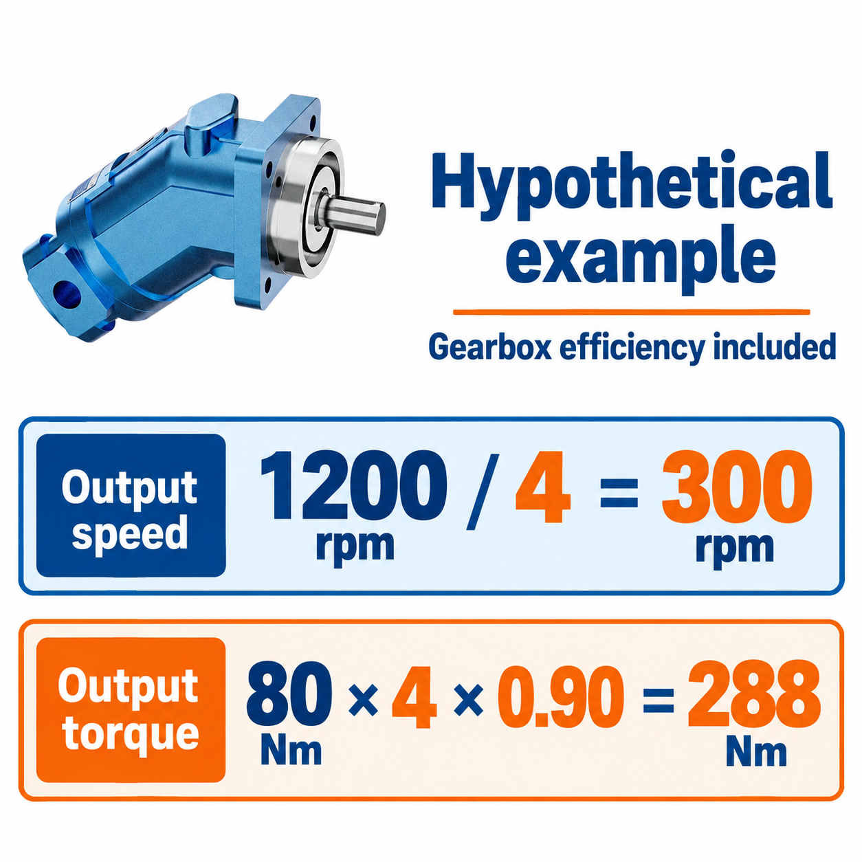
Consider a hypothetical motor delivering 80 N·m at 1,200 rpm. A 4:1 reducer with an assumed efficiency of 0.90 gives 300 rpm and approximately 288 N·m at the output: 1,200 / 4 = 300, and 80 × 4 × 0.90 = 288. These numbers illustrate the calculation only; they are not ratings for the A2FM reference product or a particular gearbox.
The motor mechanical power is approximately 80 × 1,200 / 9,550 = 10.05 kW. The load power is approximately 288 × 300 / 9,550 = 9.05 kW. Their difference, about 1 kW at this assumed operating point, becomes gearbox loss. An apparently comfortable torque selection can therefore still require thermal review, especially in an enclosed installation.
Now suppose the load needs 330 N·m at 300 rpm. The illustrated combination is inadequate at its stated motor torque. A 5:1 reducer would raise output torque to 360 N·m under the same efficiency assumption, but output speed would fall to 240 rpm if motor speed stayed at 1,200 rpm. Restoring 300 rpm requires 1,500 motor rpm, followed by a fresh flow, speed, power, and thermal check. Changing ratio does not remove the original demand.
Translate the gearbox choice into hydraulic demand
Once a candidate ratio is identified, calculate required motor torque as T_motor = T_load / (i × eta_g). Determine motor speed from n_motor = i × n_load. Those two values describe the mechanical operating point to discuss with the motor supplier. They do not establish the required pressure or flow until motor displacement and efficiencies are considered.
For an initial estimate, actual inlet flow Q in L/min is approximately displacement V in cm³/rev multiplied by speed n in rpm, divided by 1,000 and by motor volumetric efficiency. Mechanical output torque is approximately pressure differential in bar multiplied by displacement in cm³/rev and motor mechanical efficiency, divided by 20π. Keep gearbox efficiency separate from motor efficiency so the same loss is not counted twice.
Use pressure across the motor, rather than pump gauge pressure alone. Directional valves, hoses, filters, and return pressure consume part of the available pressure budget. A ratio that appears satisfactory at the pump relief setting may fail under load because the motor sees less differential pressure. Check the simultaneous flow and pressure available from the power unit, rather than combining separate maximum values from unrelated operating points.
Compare candidate ratios across the complete duty
The following decision table is qualitative. It organizes checks rather than prescribing universal service factors or efficiency values. The speed and torque relationships above are grounded in the university references; permissible limits still come from the actual component documentation.
| Candidate or condition | What changes | Required check before acceptance |
|---|---|---|
| Higher reduction ratio at fixed load speed | Motor speed rises and required motor torque falls | Motor maximum speed, available flow, reducer input speed, and losses |
| Lower reduction ratio at fixed load speed | Motor speed falls and required motor torque rises | Starting torque, stable low-speed operation, pressure budget, and motor displacement |
| Frequent loaded starts | Repeated transient torque and heat replace a simple steady duty | Gearbox application rating, motor starting performance, and cycle duration |
| Reversing or overrunning load | Torque direction, backlash effects, and energy flow change | Reversing duty, braking arrangement, backdriving behavior, and protected stopping |
| Sprocket or pulley on output shaft | Output bearings carry an external force as well as torque | Overhung and axial load ratings at the actual load location |
| Long operation in a warm enclosure | Losses accumulate with limited heat rejection | Gearbox thermal capacity, lubrication, oil temperature, and cooling provisions |
Compare at least the normal point and the most demanding credible point. Record why one combination was rejected. This makes later substitutions easier to assess and prevents a purchaser from treating the cheapest matching flange as an equivalent drive.
Account for acceleration, inertia, and reversal
The load torque during acceleration includes process resistance and inertial torque. For a rigid ideal reducer, inertia at the output reflected to the motor is J_load / i². The motor-side inertia of the reducer, motor rotor, coupling, and other rotating parts must then be included. This relationship helps compare architectures; it does not predict a complete hydraulic transient.
A higher ratio can reduce reflected load inertia while increasing motor speed for the same load speed. That motor must still accelerate its own rotor, and the hydraulic circuit must supply the changing flow and torque without unacceptable pressure or inlet conditions. Backlash, elastic couplings, hoses, valve behavior, and control settings can dominate how smoothly the machine starts or reverses.
Do not infer a holding function from reduction ratio. A reducer may backdrive, and assumptions about self-locking depend on the specific mechanism and operating conditions. Suspended or potentially moving loads need an engineered holding and stopping arrangement. Relief valves and a stopped command alone do not establish that function. Isolate stored energy and mechanically secure the load before working on the coupling or output shaft.
Check the mechanical interface and lubrication
A compatible-looking flange is insufficient. Confirm pilot diameter, bolt pattern, shaft form, engagement length, coupling arrangement, allowable misalignment, and access for assembly. Establish which component locates the coupling axially. Incorrect axial restraint can load bearings even when a torque calculation is correct. Request an assembly drawing that identifies tolerances and support conditions.
Gearbox mounting orientation affects lubrication and sometimes the required oil quantity or vent position. Motor case drainage is a separate requirement governed by the selected motor configuration. Keep gearbox lubricant and hydraulic fluid requirements distinct. Avoid assuming that the two housings share lubrication because the units are bolted together.
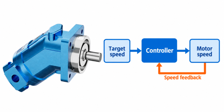
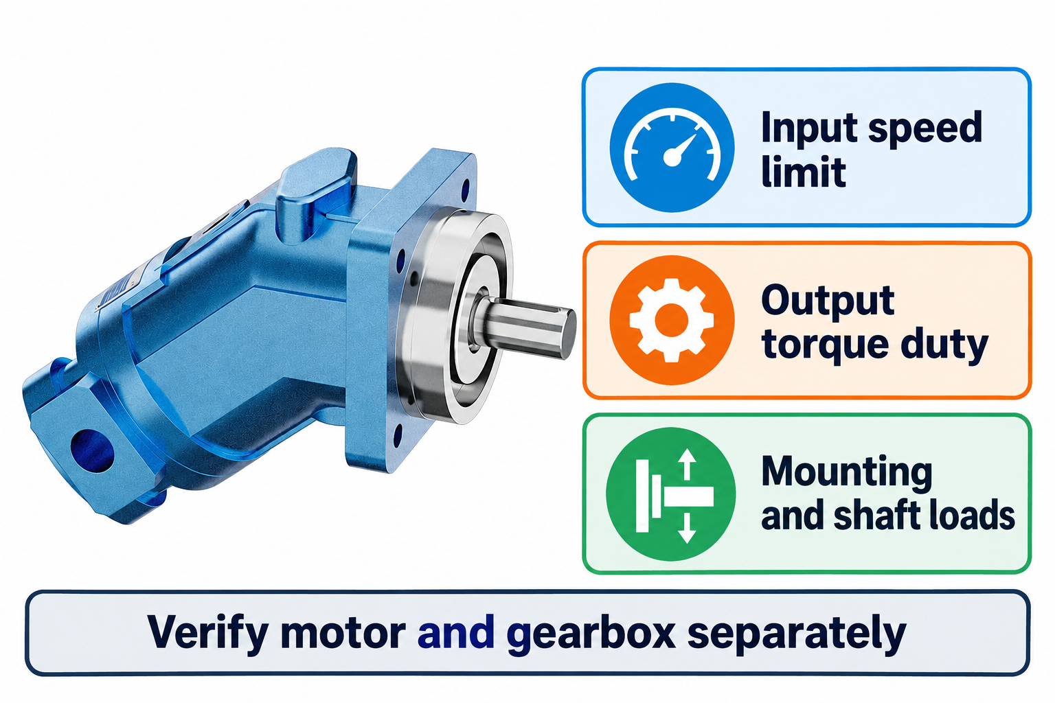
Prance’s A2FM page provides a real fixed-displacement bent-axis motor reference for discussing the motor side of this selection. Its exterior photograph establishes the visible product form, not a supplied motor-and-gearbox package, a particular coupling, or an approved shaft-load capability. The gearbox remains a separately specified component unless the quotation explicitly defines a tested assembly.
Build an RFQ that suppliers can evaluate
Provide a short duty description plus a load-speed and load-torque schedule. Include start conditions, starts per hour, rotation direction, reversals, expected service hours, ambient range, and space constraints. State whether the load can drive the motor during deceleration. Attach the interface drawing and identify any radial or axial forces at the output.
For the hydraulic side, provide available flow versus pressure, fluid and viscosity range, expected oil temperature, case-drain conditions where applicable, and the intended control method. Ask the motor supplier to identify the operating region used for selection. Ask the gearbox supplier to state continuous and intermittent ratings, thermal assumptions, efficiency basis, lubrication, and application factors. Do not invent a generic service factor when the supplier’s rating method is unknown.
During acceptance, measure output speed and direction under controlled conditions, then compare observed pressure, flow, temperature, and vibration with the approved test plan. Guard couplings and rotating shafts. Record load and oil temperature with the measurements so a later retest has a meaningful baseline. A no-load run can confirm rotation and obvious assembly issues; it cannot demonstrate loaded thermal capacity or peak-duty suitability.
Frequently asked questions
Does a higher gearbox ratio always improve a hydraulic drive?
No. It increases torque multiplication but requires greater motor speed for the same load speed. That can raise flow demand or exceed motor and gearbox input-speed limits. Compare the complete operating envelope, including efficiency, starting behavior, and thermal duty.
Should gearbox efficiency be applied to output speed?
No. Use the mechanical ratio to calculate speed. Apply forward-drive efficiency to transmitted power and available output torque. A separate backdriving condition may require different information from the reducer supplier.
Can I select the motor from load torque divided by ratio?
That is only an ideal first step. Include gearbox efficiency, then verify motor torque at available differential pressure, required flow at speed, starting conditions, duty cycle, case conditions, and mechanical interface limits.
Is a reducer a substitute for a holding brake?
Do not assume so. Holding depends on the specific reducer, load, and protective system. Obtain an engineered holding arrangement for loads that can move dangerously and secure the load during maintenance.
What information matters most in a motor-and-gearbox enquiry?
Provide output torque and speed throughout the duty, starts and reversals, hydraulic supply conditions, external shaft loads, and interface drawings. Require separate confirmation of motor operating limits and gearbox mechanical and thermal ratings.
Product and related engineering resources
The Fixed Displacement Motor A2FM catalog exterior is used as the real product reference in these explanatory images. It does not establish the approved service method, optional construction, or operating limits for an individual order. Confirm the complete code and its documentation. Related resources: Fixed Displacement Motor A2FM, hydraulic motor range, Hydraulic Motor Power Calculation: Torque, Speed, and Efficiency, Radial Piston Motor Working Principle: Torque at Low Speed.
Sources and limits of this guide
University references support the stated physical and control principles; the NIOSH source supports hazardous-energy precautions. Calculations are explicitly hypothetical. No linked source supplies ratings, wiring, approval, or a validated installation for the illustrated Prance product.
- Jönköping University Applied Mechanics: gear kinematics, rotational power, and efficiency
- UC San Diego MAE 3: gear ratio and the torque-speed tradeoff
- NPTEL: Industrial Oil Hydraulics and Pneumatics, motor and fluid-power principles
- NIOSH: preventing injuries from hazardous energy
University lesson: operating principles
NPTEL-NOC IITM presents 6.3 – Hydraulic Motors. The lesson supports the hydraulic input and motor shaft output relationships before the separately calculated gearbox reduction used in this discussion; it is not a model-specific performance or installation approval.