Wenzhou Prance Hydraulic Equipment Co., Ltd

Proportional Valve Position-Feedback Faults: Command vs Actual Position
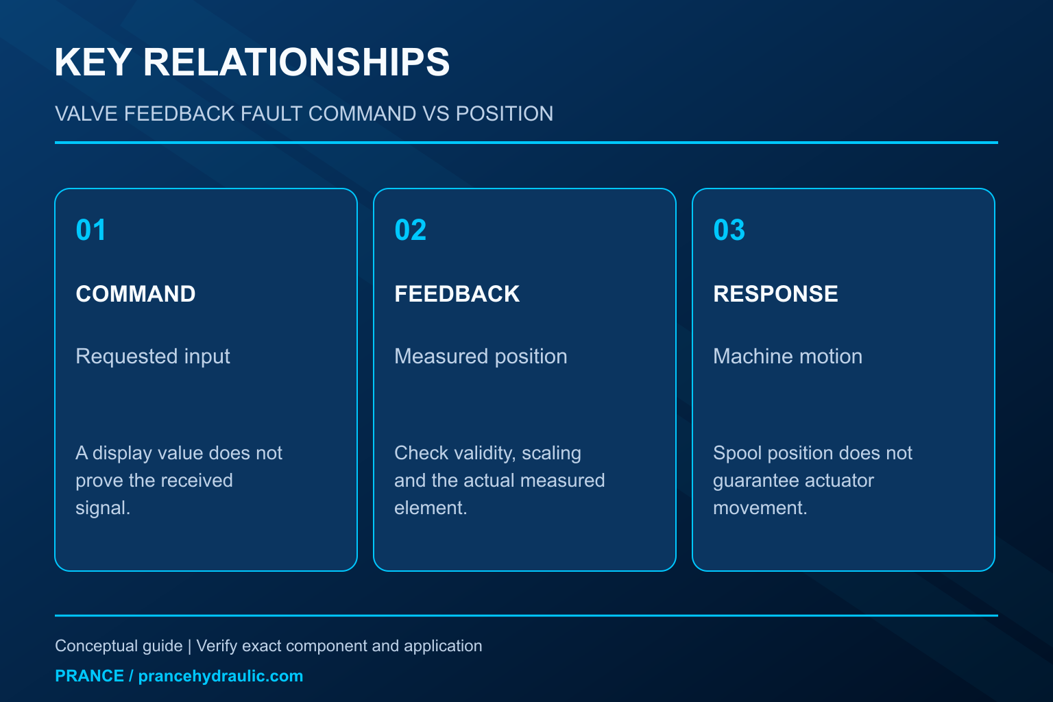
A proportional valve position feedback fault means the control system cannot establish the expected relationship between a requested valve position and a valid measured position. It does not automatically mean the spool is mechanically stuck. An incorrect command scale, missing supply, damaged cable, invalid feedback signal, amplifier state, or actual spool movement problem can produce similar symptoms. Begin by identifying which signal the alarm monitors and where it is measured. Compare command, measured spool position, and hydraulic response as three separate observations before deciding to replace the valve.
This guide concerns diagnostic reasoning for a proportional directional valve with position feedback. It provides no universal connector pinout, voltage range, alarm delay, or calibration instruction. Those details belong to the complete valve and electronics code.
Identify which position the system actually measures
A valve’s internal position transducer generally measures a component within the valve, such as a spool or actuator element. An external machine sensor may instead measure cylinder travel, motor speed, or another process variable. These measurements belong to different control loops. A cylinder failing to reach its target is not proof that the spool-position transducer has failed.
Confirm the actual architecture. Some valves use integrated electronics; others depend on a separate amplifier or controller. Feedback may remain internal to the electronics, may be available as a monitor output, or may be transmitted through a configured interface. A display value called actual position could even be a calculated variable rather than a direct sensor measurement.
Read the schematic, electronics manual, and parameter configuration together. The NPTEL electrohydraulic-valve lecture explains the general use of position transducers and feedback. It does not establish the wiring or signal interpretation for a particular Prance 4WREE valve. An identical-looking connector is insufficient evidence of electrical interchangeability.
Separate the command path from the feedback path
The command is the requested operating value. Feedback is an observation used to evaluate or control the response. A PLC command percentage only proves what the PLC intends to send. It does not prove the signal reaching the valve, its reference potential, or whether the amplifier is accepting it.
Likewise, a monitor output is not automatically an unconditioned transducer signal. It can be scaled, filtered, limited, or subject to fault handling. A fixed reading can therefore mean a fixed mechanical position, a disabled output, a disconnected signal, or a substituted diagnostic value. The manual must identify which interpretation applies.
For a safe, approved test, compare the requested command, the command observed at the permitted measurement point, and the reported feedback at the same time. If one is in percent and another in volts or digital counts, convert them only with the documented scaling. An apparent mismatch created by comparing unlike units is a reporting error, not a valve defect.
Use the alarm definition before changing the hardware
A following-error alarm may compare command and feedback over a configured duration. A sensor-validity alarm may instead check whether feedback is electrically plausible. A communications alarm may indicate that the controller has no current feedback data at all. These events require different checks even when the operator screen uses similar wording.
Preserve the exact alarm text, occurrence time, operating mode, and any diagnostic code before resetting. Note whether the fault appears at power-up, after enable, during movement, or only under load. A power-up fault with no motion request suggests a different investigation from a mismatch that develops only during a demanding transition.
Do not increase the permitted error or delay merely to suppress the alarm. Such a change can hide a condition the machine was designed to detect. First establish that the settings match the approved configuration. If the original configuration is unknown, obtain it rather than reverse-engineering a safety decision from the present behavior.
A decision table for the first distinctions
| Observed evidence | First question | Appropriate next check |
|---|---|---|
| Feedback is invalid before enable | Is the supply, connection, or measurement valid? | Verify approved supply and diagnostic definitions |
| Command display changes but received command does not | Is the command path intact and correctly configured? | Compare controller output with the documented valve input |
| Received command is valid but feedback remains fixed | Is motion inhibited or feedback unavailable? | Check enable state, amplifier diagnostics, and permitted sensor tests |
| Feedback follows command but actuator does not respond | Is the issue downstream of spool positioning? | Review supply, metering path, load, and actuator conditions |
| Mismatch appears only during transitions | Is this a dynamic limitation or a persistent error? | Compare synchronized traces and documented settling behavior |
This qualitative table does not define pass limits. Follow the specific electronics and machine procedure. A permitted monitoring point is essential: applying test voltage to an unknown pin, unplugging a powered sensor, or injecting a substitute signal can damage electronics or cause unintended movement.
Check power and connections without guessing pin assignments
A connection can appear intact while a supply falls outside the permitted range under load. The relevant reading is at the documented point under the required condition, measured with suitable equipment. A power-supply label or an unloaded cabinet reading does not establish the voltage available to the valve electronics during operation.
Inspect accessible cable condition, connector retention, moisture evidence, and strain after safe isolation. Confirm cable type and shielding against the manufacturer’s requirements. Do not assume that joining every shield or reference to a convenient chassis point will improve the signal; the correct arrangement depends on the electrical design.
A recent cable or valve replacement deserves particular attention. Compare full order codes and revisions, not just connector shape or the first series characters. Current versus voltage command options, enable logic, monitor functions, and communication configuration can differ. Retain the removed component and original configuration until compatibility has been established.
Distinguish a stationary spool from an unreliable measurement
A fixed feedback value cannot prove that the spool is physically fixed. The feedback path itself may be faulty or the reported value may not be current. Conversely, a changing feedback display does not prove that every hydraulic metering edge is producing the intended flow. Treat the display as one piece of evidence.
Use only the diagnostic methods authorized for the specific valve. Some electronics provide internal error information or defined monitor behavior. Other systems require a service tool or supplier test facility. Do not open a sealed transducer, loosen its adjustment, or move a core to make the displayed zero look correct.
If the evidence supports mechanical sticking, investigate contamination, fluid condition, pressure conditions, and the machine history under the applicable procedure. A feedback alarm alone is not sufficient evidence to dismantle the valve. Precision components can be damaged by improvised cleaning, abrasive work, or uncontrolled disassembly, and the original cause may remain in the circuit.
Read hydraulic response as a separate layer
Spool position changes a metering opening, but resulting flow also depends on the pressure difference and the available supply. A valve can report a plausible position while the actuator remains stationary because the load cannot be overcome, the supply is unavailable, or another valve blocks the path. This is a hydraulic-response problem until evidence establishes a feedback defect.
Check the relevant supply and work-port conditions through approved test points. Include any pilot and drain requirements if the actual design has them. Do not assume every proportional valve is pilot operated, and do not apply another series’ minimum pilot pressure to a direct-operated valve.
Also distinguish spool center from a guaranteed machine holding state. Internal leakage, center configuration, external load-control devices, and the complete circuit determine motion behavior. Never rely on a feedback display near zero as the sole means of securing a suspended or driven load. Use the machine’s required isolation and load-restraint measures.
Separate static error, lag, and repeated disturbances
A steady mismatch after the permitted settling period differs from a brief mismatch during movement. Rapid commands may exceed the available dynamic response, while filters, ramps, and controller limits can intentionally shape the transition. A single snapshot cannot establish whether the valve eventually reached the requested position.
Capture command and feedback on a shared time basis where the approved instrumentation supports it. Include enable state, relevant supply conditions, and alarm timing. If instruments cannot capture the event reliably, report that limitation instead of assigning a cause from unsynchronized readings.
Repeated oscillation can involve the complete control loop rather than only the sensor. Raising gain or changing dither without the approved commissioning method can worsen movement or heating. Preserve the existing settings, identify the configuration baseline, and involve the responsible controls or hydraulic specialist before tuning. A successful alarm reset is not evidence that the original mismatch has been corrected.
Define the supplier decision and verify the correction
The Prance Hydraulic Proportional Valve with Position Feedback 4WREE is a relevant product category for this investigation. The category name does not establish the particular sensor, connector assignment, electronics option, or fail-state behavior of an ordered unit. Confirm those details using the complete code and matching documents before a replacement is selected.
Provide the supplier with the full nameplate code, electronics revision, command type, supply measurements, diagnostic message, and synchronized observations. State whether the feedback is invalid, fixed, delayed, or inconsistent, and whether the hydraulic response agrees with it. That distinction directs attention toward the signal path, movement control, or downstream circuit.
After repair, verify normal operation through the approved commissioning sequence, including the original fault condition where it can be reproduced safely. Confirm correct direction, stable response, valid feedback, and required fault handling. Restore all covers, protective settings, and documented configurations. Keep the before-and-after evidence so that a later recurrence can be compared without repeating the entire investigation.
FAQ
Does a position-feedback fault always mean the LVDT has failed?
No. The alarm may arise from the command path, supply, enable state, configuration, communication, or actual movement. Establish what the alarm evaluates before assigning a sensor failure.
Can a spool-position signal prove that the cylinder is in position?
No. Spool and actuator positions describe different components and often different loops. Cylinder motion also depends on flow, load, leakage, and the rest of the hydraulic circuit.
Should I adjust feedback zero until the alarm disappears?
No. An undocumented adjustment can hide a fault and alter control behavior. Use the exact manufacturer’s calibration procedure only when the diagnosis and authorization call for it.
Can two valves with the same connector be exchanged?
Connector appearance does not establish compatibility. Confirm the complete order code, supply, signal type, enable logic, electronics, hydraulic function, and configuration before substitution.
What evidence is most useful for an intermittent fault?
A time-aligned record of received command, feedback, enable state, supply conditions, and alarm occurrence is more useful than separate snapshots. Include the operating load and configuration without inventing missing measurements.
Product and related engineering resources
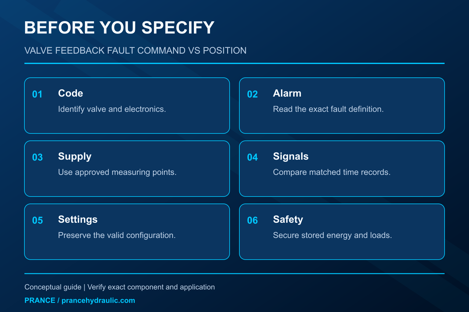
The Hydraulic Proportional Valve With Position Feedback 4WREE is the relevant product category for this guide. The illustrations explain concepts and do not depict the product internals or establish operating limits. Confirm the complete code and approved documentation. Related resources: Hydraulic Proportional Valve With Position Feedback 4WREE, hydraulic valve range, Hydraulic Proportional Valve with Position Feedback: Selection Guide, Hydraulic Valve Null Adjustment: Servo and Proportional Controls.
Sources and limits of this guide
General engineering principles are separated from product facts. Numerical examples are hypothetical, not Prance ratings. Proprietary client writing templates and parameter-table originals were not supplied.
- NPTEL: Fundamentals of Industrial Oil Hydraulics and Pneumatics
- NIOSH: preventing injuries from hazardous energy
- NPTEL lecture: electrohydraulic valves and feedback principles
University lesson: operating principles
NPTEL-NOC IITM presents 5.4 – Directional Control Valves. The lesson supports the directional spool operation; supplementary background, not a feedback-fault tutorial used in this discussion; it is not a model-specific performance or installation approval.