Wenzhou Prance Hydraulic Equipment Co., Ltd

Sizing a Proportional Valve for a Hydraulic Motor: Flow and Pressure Budget
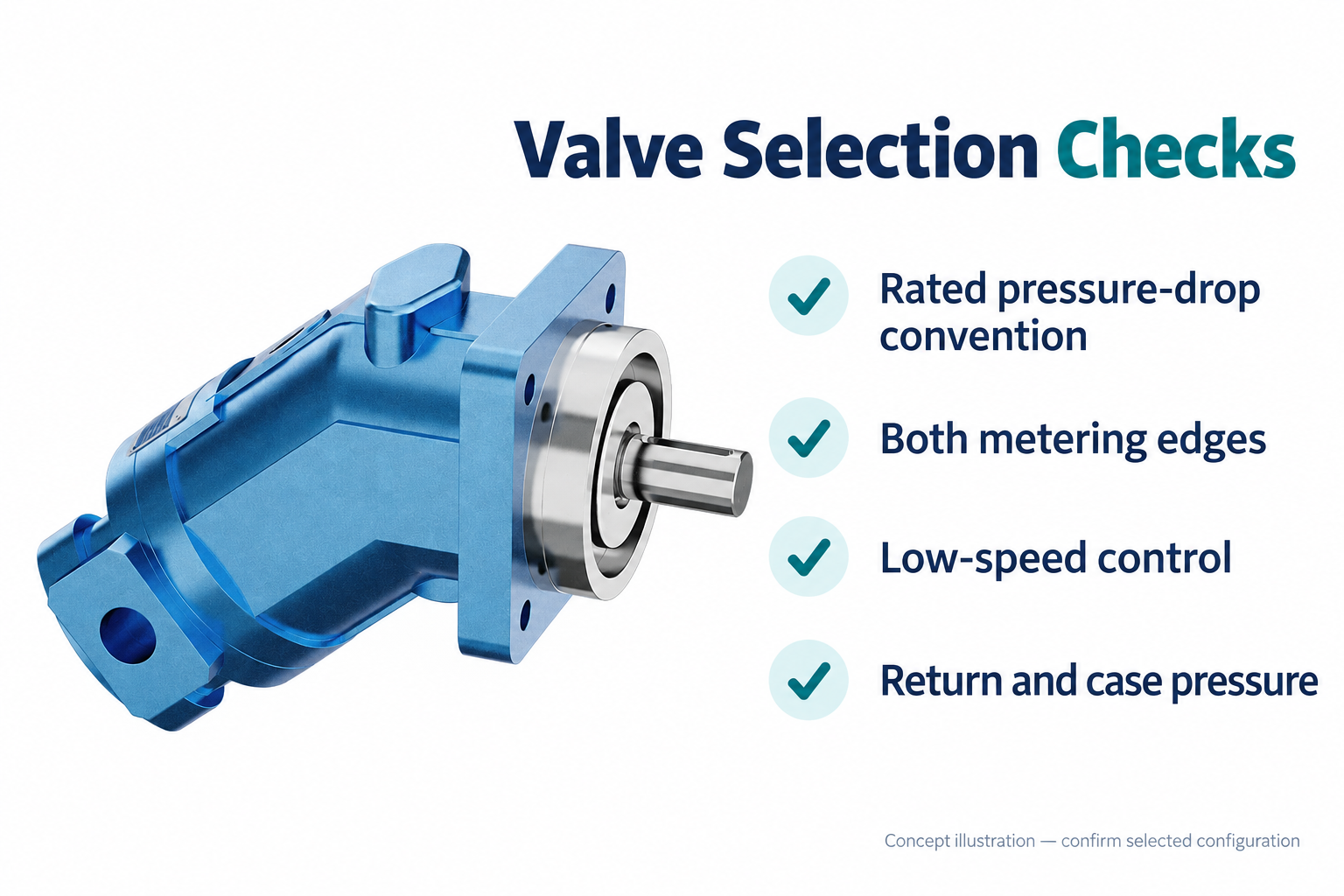
Hydraulic motor proportional valve sizing starts with the motor’s required inlet flow and the pressure available for metering after the load and the rest of the circuit are supplied. Choose a valve that can deliver that flow at the actual pressure drop, while retaining useful control at the lowest required speed. A catalog flow number by itself is insufficient because its stated test pressure drop may differ from your circuit. Check both metering edges, return pressure, motor case pressure, thermal loss, and load behavior before approving a valve. The largest nominal valve is not automatically the best speed-control choice.
Translate the motion requirement into motor flow
Define the motor speed range, displacement, load torque, direction changes, and operating duty. For a fixed-displacement motor, approximate inlet flow as Q = Vd × n/(1000 × ηv), with Q in L/min, displacement in cm³/rev, speed in rpm, and volumetric efficiency as a fraction. Use the motor supplier’s efficiency information for the relevant speed, pressure, temperature, and oil rather than a universal value.
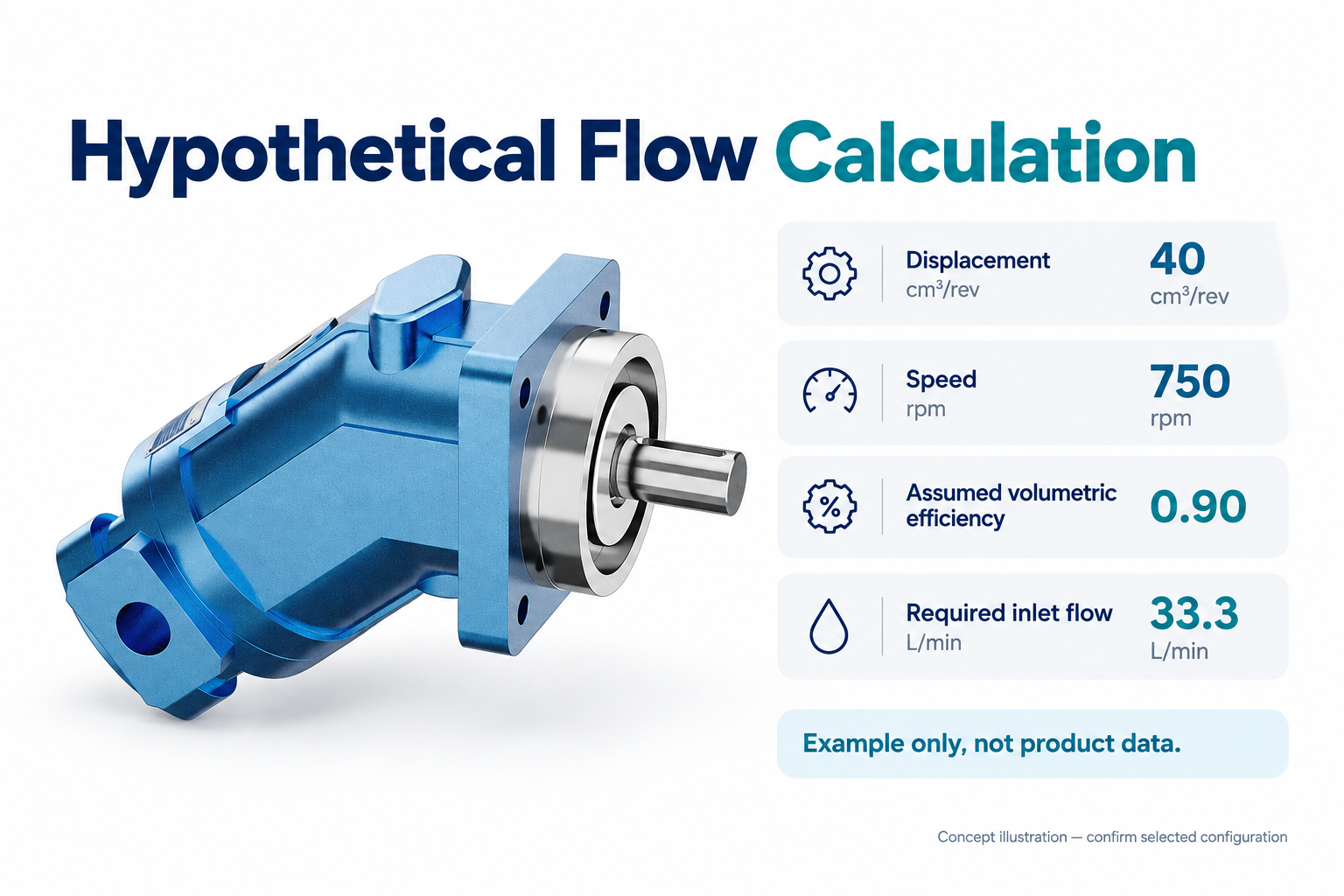
As a hypothetical example, a 40 cm³/rev motor at 750 rpm with an assumed volumetric efficiency of 0.90 requires approximately 33.3 L/min. Its geometric flow is 30 L/min; the difference represents the simplified allowance for internal leakage. This example demonstrates the calculation only. It is not performance data for the A2FM product pictured in this guide.
Calculate the low-speed point as well as the maximum. Leakage may become a large share of inlet flow at low speed, and friction can make motion uneven. A valve sized only for peak flow may provide a very small useful command range near the minimum speed. The low-speed requirement should therefore be expressed as a measurable operating condition, not simply a percentage of maximum speed.
Build the pressure budget around the load
Estimate the pressure difference needed across the motor for the load torque using the selected motor’s data. The ideal torque relationship is T = Δp × Vd/(2π). A real motoring calculation accounts for mechanical efficiency, while overrun requires a different operating-quadrant assessment. Keep the pressure difference across the motor distinct from the absolute pressures at its two working ports.
Next account for line losses, filters, coolers, return routing, and other components in the selected flow path. The remaining pressure difference is available to the controlling valve, subject to the supply architecture and operating condition. Repeat the budget at relevant load and speed combinations. A system with adequate supply pressure at one working point may have little metering reserve at another.
A pressure-compensated pump, a fixed pump with a relief path, and a load-sensing arrangement do not behave identically as valve demand changes. Identify the supply concept before relying on a single available-pressure figure. The valve must be compatible with that concept and with other branches operating at the same time. Simultaneous demand can alter both pressure reserve and available flow.
Read the catalog flow convention precisely
A proportional directional valve’s rated flow is normally stated with a particular pressure-drop convention and test condition. Some documentation describes one metering edge; other documentation describes the complete path or a specified total valve pressure drop. Read the selected valve’s definition. Applying a total-path number to one edge can produce a substantial sizing error.
For a fixed opening under suitable conditions, an initial orifice estimate is Qactual ≈ Qrated × √(Δpactual/Δprated). Both pressure differences must use the same convention. Oil properties, spool shape, flow forces, compensation, and manufacturer operating limits can make this approximation incomplete. Use the published curves or a supplier calculation for the actual valve rather than treating the square-root relation as a complete selection model.
For example, a hypothetical opening passing 40 L/min at a 10 bar differential would pass approximately 28.3 L/min at 5 bar under the simplified relation. These numbers are not a proposed rating or a recommended operating pressure. Their purpose is to show why a flow rating cannot be detached from its test differential.
Assess both metering edges and both directions
A four-way valve controlling a motor usually meters supply to one working port and flow from the other working port to tank. Both edges contribute to pressure loss. For a motor, geometric working-port flows may be similar, but leakage paths and circuit arrangements still matter. Do not import the unequal-area flow assumptions of a cylinder without checking the actuator.
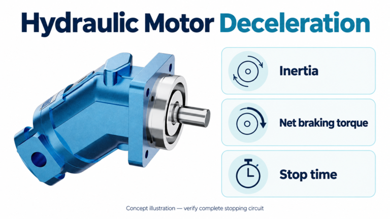
Check the reverse direction separately. Spool geometry, available paths, external check functions, and load direction can make the two directions behave differently. A reversible motor may also encounter overrun during deceleration or a driven load. Selecting a valve for steady motoring flow alone does not establish adequate braking or makeup behavior.
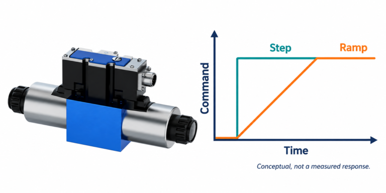
Review neutral behavior and the transition between directions. Closed, open, and other center arrangements have different consequences for trapped oil, supply unloading, and coast-down. Identify the required machine behavior first, then obtain the correct spool and circuit design. The exterior appearance of a proportional valve does not reveal its complete hydraulic function.
| Selection question | Required evidence | Common sizing mistake |
|---|---|---|
| What is peak inlet flow? | Motor speed, displacement, leakage basis | Using geometric flow as exact demand |
| What differential is available? | Load and complete circuit pressure budget | Assigning all supply pressure to the valve |
| What does rated flow mean? | Exact catalog test convention | Mixing one-edge and total-path ratings |
| Can minimum speed be controlled? | Low-command curves and validated motor behavior | Choosing the largest nominal flow |
| What happens during overrun? | Circuit and operating-quadrant assessment | Treating braking as normal motoring |
| What heat is generated? | Actual flow, differential, and duty | Ignoring continuous throttling loss |
This decision table applies general fluid-power relationships from the university teaching sources below. Actual selection requires the ordered motor and valve documents; the table provides no model-specific approval.
Preserve a useful control range
A valve must cover the required maximum flow, but resolution and repeatability matter across the normal working range. If most operation occurs near a very small opening, deadband, hysteresis, contamination sensitivity, and command resolution can dominate. Ask for flow-versus-command curves at relevant pressure conditions and for the documented behavior around neutral.
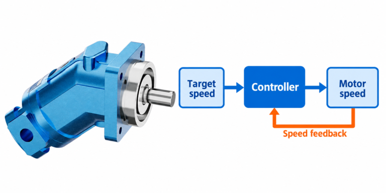
Distinguish electrical resolution from hydraulic resolution. A controller with many digital steps cannot make a valve or motor respond smoothly below its practical physical range. Similarly, encoder feedback can correct some disturbances but cannot create missing pressure reserve or eliminate all friction effects. Specify an allowable speed variation over a defined interval and load condition so the supplier can assess the complete drive.
Do not use a fixed percentage of rated valve flow as a universal selection rule. The appropriate margin depends on load transients, supply behavior, tolerances, available spool options, and the useful low-speed range. State the operating envelope and ask for a justified selection rather than an unexplained oversizing factor.
Calculate throttling loss and thermal duty
The approximate hydraulic power dissipated across a pressure drop is P = Δp × Q/600, with P in kW, pressure drop in bar, and flow in L/min. A hypothetical total valve loss of 15 bar at 33.3 L/min corresponds to approximately 0.83 kW. This is a teaching example, not a recommended differential or a prediction for a specific valve.
Evaluate the duty cycle rather than adding only the maximum power point. Continuous speed regulation can create persistent heat, while short transients may impose local peaks. Include pump losses, motor losses, other branches, and environmental conditions in the complete thermal balance. A cooler calculation for the whole system should not be replaced by the valve calculation alone.
Reducing valve differential can reduce throttling loss, but too little available differential can remove control authority at the required flow. The selection is therefore a balance between controllability, supply architecture, and heat. It cannot be solved by minimizing pressure drop without considering response under load.
Keep return pressure and case pressure separate
Measure or calculate return-line pressure at the relevant motor working port under the actual flow condition. Filters, coolers, shared return lines, and transient events may raise it. That pressure reduces the useful differential across the motor for a given supply pressure and may affect the acceptable operating envelope.
Case pressure is a separate condition governed by the selected motor’s construction and drain arrangement. Do not assume the case can tolerate the working return-line pressure, and do not route drains based on a generic drawing. Request the full motor installation instructions, including required case filling, drain routing, and permitted pressure conditions.
The A2FM catalog product associated with this article supplies a real exterior reference and an enquiry path. It does not prove that every configuration has identical drain requirements or that it is approved for the proposed proportional-control circuit. Full order-code documentation is necessary.
Specify and validate the complete branch
An effective enquiry includes the motor code and displacement, speed range, load-torque curve, supply concept, minimum and maximum supply conditions, return routing, oil, temperature range, duty cycle, and required response. Add the selected valve function, signal interface, and any feedback arrangement. Include machine stopping and power-loss requirements so they are assessed separately from normal speed control.
Acceptance should compare requested and actual speed at defined load points, pressure reserve, temperature, and low-speed behavior. Record command, speed, and relevant pressures on a common time base under an approved procedure. Use the machine’s guarding, isolation, and hazardous-energy controls. A successful no-load spin does not demonstrate performance at maximum load or safe overrun.
Frequently asked questions
Can valve rated flow equal the motor’s calculated maximum flow?
It may, but only if the rating convention and actual differential support that flow and the remaining operating range is suitable. Compare manufacturer curves with the complete circuit budget. Equal numbers on two catalog pages do not establish a matched drive.
Why does motor speed fall when load increases?
Load can reduce the pressure available for metering, increase leakage, or push the supply or controller to a limit. A fixed valve command does not necessarily hold constant flow as pressures change. Diagnose the full branch before assuming the motor displacement is wrong.
Is a bigger proportional valve always smoother?
No. A larger valve can place normal operation near a small opening where deadband and practical resolution matter more. Smoothness depends on the valve, motor, supply, feedback, and mechanical load. Check the required low-speed performance explicitly.
Can a proportional valve replace a braking valve?
A proportional metering function does not automatically provide the required load-control, holding, makeup, or power-loss behavior. Those functions require a circuit assessment with the selected components. Do not infer their presence from the ability to vary motor speed.
Which pressure belongs in the throttling-loss equation?
Use the actual pressure drop across the flow path being evaluated, consistently with its flow. If evaluating the complete valve, include the relevant supply and return metering losses. Do not substitute motor load pressure or total pump pressure without identifying the intended component boundary.
Product and related engineering resources
The Fixed Displacement Motor A2FM catalog exterior is used as the real product reference in these explanatory images. It does not establish the approved service method, optional construction, or operating limits for an individual order. Confirm the complete code and its documentation. Related resources: Fixed Displacement Motor A2FM, hydraulic motor range, Hydraulic Flow Valve: Control Actuator Speed Without Confusing Valve Types, Hydraulic Motor Case Drain Line Sizing and Connection Rules.
Sources and limits of this guide
University material supports physical and control principles; NIOSH supports hazardous-energy precautions. Numerical calculations are hypothetical. No source is used to invent a Prance rating, pinout, installation approval or optional construction.
- NPTEL Fluid Power Control: proportional valves, electrical amplifiers and command shaping
- NPTEL: Industrial Oil Hydraulics and Pneumatics
- NIOSH: hazardous-energy injury prevention
University lesson: operating principles
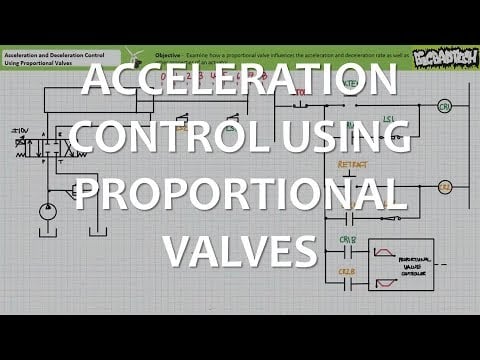
Jim Pytel presents Acceleration Control Using Proportional Valves (Full Lecture). The lesson supports the proportional valve metering and acceleration control, not model-specific sizing approval used in this discussion; it is not a model-specific performance or installation approval.