Wenzhou Prance Hydraulic Equipment Co., Ltd

Trapped Oil in Hydraulic Motor Lines: Thermal Pressure After Shutdown
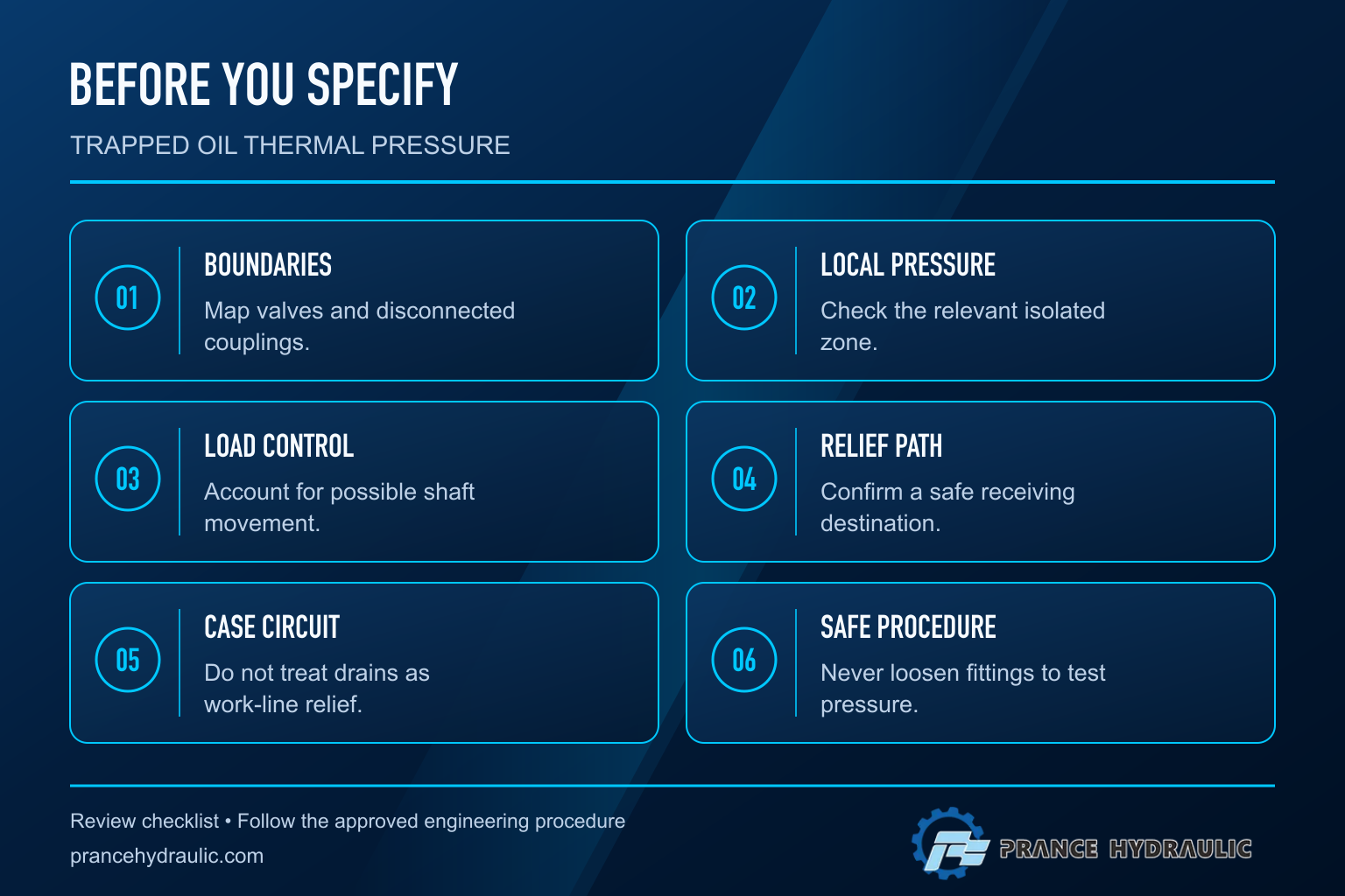
Oil trapped in a hydraulic motor circuit can develop pressure after shutdown if it warms while its available volume is constrained. Stopping the pump removes one source of energy; it does not prove that every isolated line, motor port or valve cavity is depressurized. Closed valves, disconnected couplings and load-holding devices can divide the circuit into separate pressure zones. Review each zone and its approved protection path. Never loosen a fitting to find out whether pressure remains. The correct response is controlled isolation, verification at the relevant points and an engineering review of the complete circuit.
Why a stopped motor can still have pressurized lines
A hydraulic motor converts a pressure difference and flow into shaft torque and rotation during operation. After stopping, its surrounding circuit can retain pressure from the previous load, mechanical forces or trapped fluid. A blocked directional valve or closed isolation valve may prevent that fluid from reaching the reservoir. Pressure at the pump outlet therefore does not describe every downstream zone.
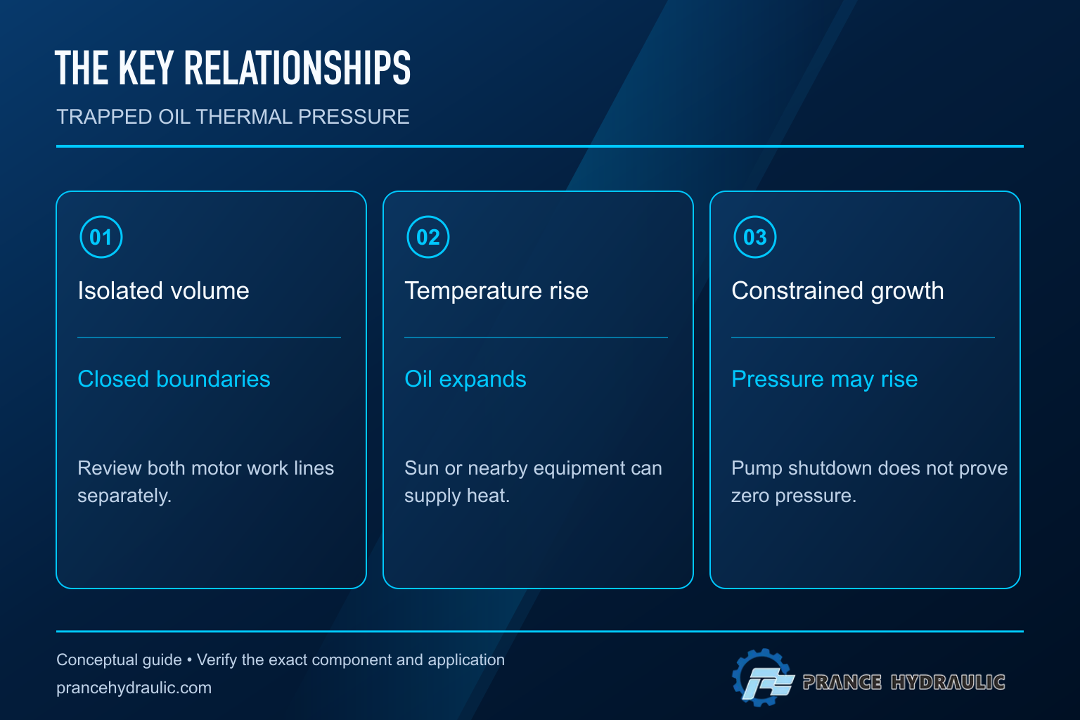
Thermal expansion adds another mechanism. Oil tends to occupy more volume when its temperature rises. If a sealed zone offers little room for that expansion, pressure can rise even without a running pump. Sunlight, a warming enclosure or nearby hot machinery may supply the heat. The exact response depends on the oil, temperature range, trapped gas, hose compliance and component deformation.
Ohio State University hydraulic safety training explicitly identifies warming of trapped hydraulic fluid as a pressure hazard. Its general warning supports the need to investigate isolated zones; it does not define a permissible motor pressure or authorize a specific relief setting. Keep those model-specific decisions with the approved component documents and machine design.
Find the boundaries of the trapped volume
Start with the circuit in its actual shutdown state. Mark directional valve positions, isolation valves, check valves, load-holding valves, couplings and any protection devices. Then identify which passages remain connected to a reservoir or an approved pressure-control path. A schematic representing normal running can be misleading if the valve states change when electrical power disappears.
Follow both motor work lines separately. Do not assume that a cross-port connection creates a reservoir path. A device that transfers oil from one line to the other can still leave the combined volume isolated. Equally, a check valve may allow supply flow but prevent the reverse movement needed to accommodate expansion. The direction and destination of every possible path matter.
Review the motor case circuit separately from the A and B work lines. A case drain is not automatically a pressure-relief path for trapped work-port oil. Internal leakage is variable and should not be treated as an engineered safety device unless the approved design explicitly relies on a documented characteristic. Never connect a work line to a case drain as an improvised solution.
Understand the pressure mechanism without inventing a rating
A simplified small-change relationship for a fully constrained liquid is Δp ≈ K × α × ΔT, where K is bulk modulus, α is volumetric thermal expansion coefficient and ΔT is temperature rise. This expression neglects container expansion, hose flexibility, gas and leakage. It explains the direction of the effect; it is not a reliable setting calculation for a real machine.
In an illustrative teaching case, assume K = 1.4 GPa, α = 0.0007 per kelvin and a 10 K rise. The simplified estimate is 9.8 MPa, or 98 bar. These input values are hypothetical, not measured properties of the installed oil and not A2FM ratings. The example shows why even modest warming deserves attention when volume change is strongly constrained.
A compliant hose can reduce the pressure rise relative to a rigid model, but that does not establish safety. Its expansion behavior changes with construction, pressure and temperature, and its allowable working pressure may also depend on temperature. Entrained gas changes the response too. Do not rely on uncertain flexibility or trapped air as protection, and do not use this example to size a relief device.
Separate four different pressure questions
| Observation | Possible mechanism to investigate | Evidence that distinguishes it |
|---|---|---|
| Pressure remains immediately after stopping | Retained load or isolated operating pressure | Shutdown valve states and local measurements |
| Pressure rises during a warm idle period | Constrained thermal expansion | Time-aligned local pressure and temperature |
| Pressure changes with shaft or load movement | Mechanical energy acting through the motor | Approved load-restraint review and motion record |
| Case pressure is abnormal | Restricted or incorrectly arranged case drainage | Separate case-circuit documentation and measurements |
| Main gauge is zero but a work line is not | Separate isolated pressure zones | Measurement locations and isolation boundaries |
These are investigation categories rather than diagnoses. A system can contain more than one mechanism. For example, a load can retain an initial work-line pressure, and later warming can increase it. A thermal explanation should not hide a mechanical load-holding problem, and a case-pressure concern should not be confused with work-port pressure.
Review thermal protection as a complete path
An engineering review should identify where pressure is sensed, where oil can go and what happens to the receiving zone. A thermal relief device cannot protect a volume that is isolated from its inlet by another closed valve. Likewise, a discharge path into another sealed volume can transfer the problem rather than resolve it.
Do not equate thermal protection with full operating-overload protection. The required flow and response for a slowly warming isolated volume can differ from the demand during a driven motor transient. A device suitable for one duty is not automatically suitable for the other. The review must also preserve any load-holding function and avoid unintended shaft movement.
Specify the relevant fluid, temperature envelope, component pressure limits, return pressure and operating states before selecting hardware. The approved design should cover power loss, disconnection and maintenance isolation where applicable. This article does not prescribe a setting or a circuit modification because the necessary component limits and load analysis are application-specific.
Investigate safely and collect useful evidence
Plan the investigation before attaching instruments. Identify stored mechanical energy, supported loads, accumulators and possible motor movement. Use the machine’s documented isolation and verification procedure, suitable instruments and competent personnel. A zero reading at one point is evidence only for the zone that point actually measures.
Record local pressure and temperature over a representative shutdown interval. Note the last loaded operating condition, ambient changes, valve positions and whether hoses or couplings were disconnected. Photographs of labels and routing can help reconcile the schematic with the installed machine. Avoid deliberately heating a sealed system to reproduce an event outside an approved test plan.
Preserve the original readings and timestamps. A report stating only that the coupling was difficult to reconnect leaves several explanations open. A rising pressure trace aligned with a warming interval is more informative, but it still requires review of sensor accuracy, mechanical load and the hydraulic boundaries. Do not infer a safe condition from the absence of visible leakage.
Handle disconnected attachments and parked machinery carefully
Disconnected motor-driven attachments can contain isolated oil even when they are physically separated from the power source. Transport, sunlight and storage can alter temperature after the original shutdown. Coupling difficulty may be a symptom of trapped pressure, but forcing the coupling or loosening a hose is not a safe diagnostic method.
Use the attachment and coupling manufacturers’ approved depressurization and reconnection procedures. Those procedures must account for potential motion and load retention. A protective arrangement on the machine side may cease to protect the attachment once the coupling is separated. Review both sides of the disconnection boundary rather than assuming that the original running circuit remains intact.
For long-term storage, keep the component’s preservation and fluid requirements separate from pressure protection. A storage cap or contamination barrier does not establish a pressure-control function. Personnel receiving a stored attachment need clear handling information so that they do not assume that an idle assembly contains no stored energy.
Put the motor inquiry in the right context
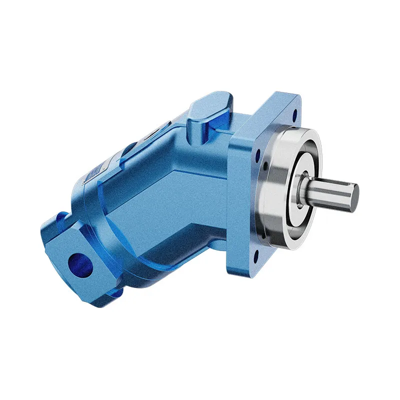
The Prance A2FM series is a fixed displacement axial piston motor category suitable for discussing work-line energy conversion. Its catalog exterior does not reveal the shutdown isolation arrangement, thermal-relief hardware or complete case-drain requirements of a particular machine. Confirm the exact motor code and its approved documentation before assigning limits.
Send the supplier a shutdown-state schematic, the trapped-zone map, relevant motor and valve codes, fluid details and a pressure-temperature record. State whether the concern occurs while parked, disconnected or during maintenance. That context directs the review toward the actual hazard rather than a general motor replacement request.
Keep this topic distinct from running back pressure and cooling-load calculations. Running losses concern energy dissipated while flow and rotation occur. Thermal pressure in a closed idle zone concerns constrained volume change. Both can involve temperature, but they require different measurements and different design questions.
Frequently asked questions
Can trapped oil pressure rise with the pump switched off?
Yes. Warming of constrained oil can increase pressure without pump flow. Retained loads and other stored energy may also affect the pressure, so the complete circuit must be reviewed.
Does a zero pump gauge prove the motor lines are safe?
No. Closed valves or couplings can separate the motor lines from the gauge. Verification must address the relevant isolated zones using the approved procedure.
Can the case drain relieve trapped work-line pressure?
Do not assume that it can. Case drainage and A/B work lines perform different functions. Internal leakage is not a substitute for an approved thermal protection path.
Is a cross-port relief always enough?
No. Its suitability depends on the complete arrangement, including whether it can reach the trapped volume and whether the receiving line can safely accommodate the transferred oil.
Should a tight coupling be loosened to release pressure?
No. Do not loosen a pressurized fitting as a test or workaround. Follow the approved attachment and coupling procedures, with stored loads controlled and pressure safely verified.
Product and related engineering resources
The Fixed Displacement Motor A2FM is the relevant product category for this guide. The illustrations explain concepts and do not depict the product internals or establish operating limits. Confirm the complete code and approved documentation. Related resources: Fixed Displacement Motor A2FM, hydraulic motor range, Hydraulic Motor Case Pressure: Limits and Seal Failure Prevention, Radial Piston Motor Working Principle: Torque at Low Speed.
Sources and limits of this guide
Educational principles and explicitly hypothetical calculations only. No pressure, time limit, internal geometry, thermal-relief setting or performance curve is assigned to a Prance product. Actual service and selection require the approved data sheet for the complete order code and circuit review.
- NPTEL: Industrial Oil Hydraulics and Pneumatics
- NIOSH: hazardous energy prevention
- Ohio State University: Safe Use of Hydraulic Systems
- NPTEL: fluid compressibility and bulk modulus
University lesson: operating principles
NPTEL-NOC IITM presents 6.3 – Hydraulic Motors. The lesson supports the hydraulic motor energy conversion; the lesson does not approve a thermal-relief arrangement used in this discussion; it is not a model-specific performance or installation approval.