Wenzhou Prance Hydraulic Equipment Co., Ltd

Hydraulic Pump Inlet Conditions: A Buyer Checklist Before Ordering
Hydraulic pump inlet conditions are a system check, not a single pressure number: confirm pressure at the pump inlet, suction-line losses, reservoir arrangement, fluid viscosity and temperature, and exclusion of air. Compare the completed check with the selected pump’s technical documentation before ordering.
Contents
- Part 1. What do hydraulic pump inlet conditions mean?
- Part 2. Which pressure must be checked at the pump inlet?
- Part 3. How do suction line and reservoir layout affect supply?
- Part 4. Why do fluid viscosity, temperature and filtration matter?
- Part 5. How can air entry and commissioning evidence be controlled?
- Part 6. What should a buyer send with a pump RFQ?
Part 1. What do hydraulic pump inlet conditions mean?
Inlet conditions describe whether fluid can reach the pump inlet in the quantity and state required at the planned operating point. The relevant system inputs include inlet pressure at the pump, flow, shaft speed, pipe geometry, reservoir level, fluid viscosity, temperature and possible air entry.
This check matters before model selection because a nominal flow calculation does not prove that the pump chambers can be supplied correctly. Parker’s installation guidance asks users to check inlet conditions along with speed, pressure, temperature, fluid quality, viscosity and rotation.
Part 2. Which pressure must be checked at the pump inlet?
Measure or calculate pressure at the pump inlet connection under the intended duty, then compare it with the requirement in the selected pump documentation. A gauge reading elsewhere in the tank or line cannot by itself represent the pressure available at the inlet flange after line losses.
Do not copy a pressure figure from a different manufacturer, fluid or pump series. Parker publishes inlet-pressure conditions for its own products and test conditions; those figures demonstrate why a model-specific comparison is necessary, not a Prance operating limit.
Part 3. How do suction line and reservoir layout affect supply?
Line length, internal diameter, bends, fittings, valves and any restriction affect the pressure available at the pump inlet. Parker’s truck-hydraulics guidance notes that long inlet lines, low inlet pressure and low temperature can require a larger line dimension or lower pump speed.
Reservoir conditions also belong in the review. Confirm the minimum oil level through the machine cycle, the vertical relationship between tank and pump, and whether return flow or local turbulence can disturb the suction area.
Part 4. Why do fluid viscosity, temperature and filtration matter?
Fluid state changes inlet-side behavior. Record the fluid type, viscosity range and cold-start and normal operating temperatures, then use the selected pump documentation to decide whether the planned inlet arrangement remains acceptable.
Filtration needs the same discipline. A suction-side element can add restriction as fluid temperature changes or contamination accumulates. Parker’s service guidance does not recommend an inlet strainer for its cited vane-pump application unless necessary; that is a design prompt to obtain supplier guidance, not a rule for every hydraulic pump.
Part 5. How can air entry and commissioning evidence be controlled?
Check every suction-side joint, seal and hose connection for a possible air path. Parker’s service material also calls attention to air trapped in a suction line, low oil level and suction placement near disturbed return flow when investigating inlet problems.
Before release, retain a commissioning record that identifies the pump inlet measurement location, fluid temperature, speed, observed noise or aeration, and the duty point. This evidence helps separate a plumbing issue from a model-selection question.
For a broader flow-and-speed calculation, see the hydraulic pump flow calculation guide. Application architecture can also be reviewed in the open-loop variable-displacement pump guide.
Part 6. What should a buyer send with a pump RFQ?
Provide the supplier with a concise inlet-condition record:
- required continuous and peak flow, plus shaft speed range;
- pressure duty and duty-cycle description;
- fluid type, viscosity range, cleanliness target and temperature range;
- reservoir level, pump elevation and intended inlet routing;
- suction-line internal diameter, length, fittings, valves and filter details;
- inlet pressure measurement or calculation at the pump connection;
- mounting, shaft, rotation and control requirements; and
- application, quantity and required documentation.
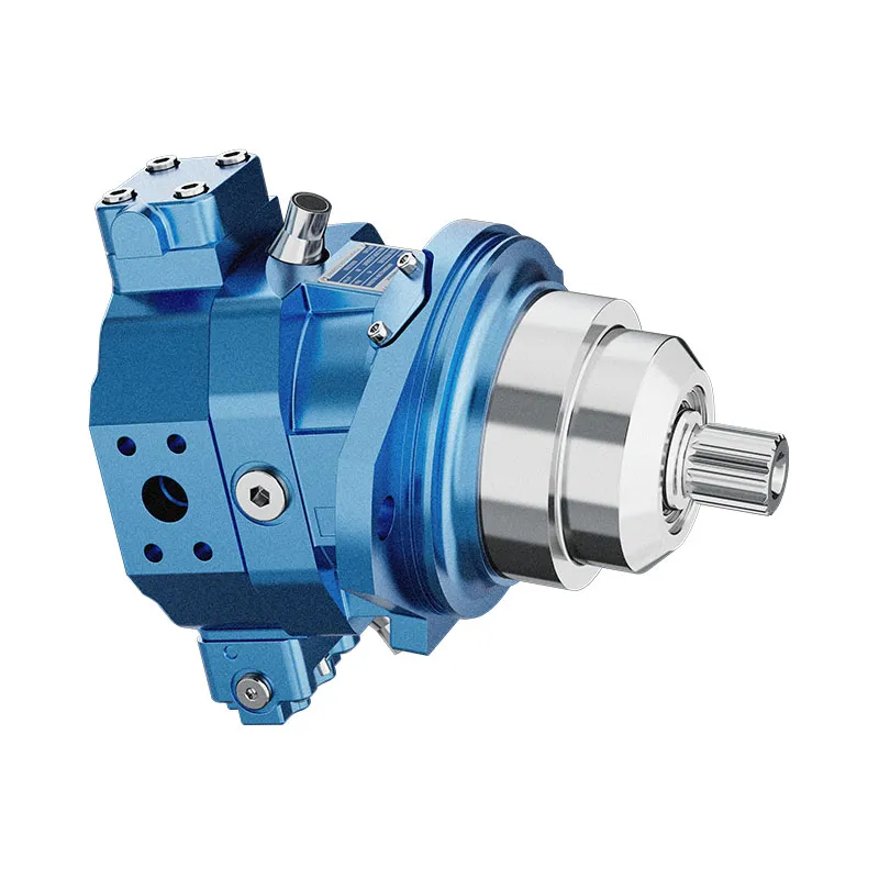
Use the variable displacement piston pump A20VO page as a product route after those inputs are documented. It is not a recommendation for a particular size or configuration: the matching datasheet and RFQ review must confirm fit. Send the complete record through the contact page.
FAQs
What are hydraulic pump inlet conditions?
They are the pressure, flow-path, reservoir, fluid and air-control conditions that determine whether fluid reaches a pump inlet as required at the operating duty.
What causes low inlet pressure at a hydraulic pump?
Potential contributors include line restriction, long routing, low reservoir head, unsuitable fluid state and excessive demand. Confirm the actual condition at the pump inlet and consult the selected model documentation.
How should a suction line be sized?
Size it from the intended flow, fluid condition, routing and pump requirement. Use supplier documentation rather than treating another pump series’ velocity guidance as a universal limit.
Can a suction strainer cause cavitation?
It can add inlet restriction, particularly as conditions change. Whether it is acceptable depends on the selected pump, fluid, element condition and the complete inlet-pressure assessment.
What fluid information is required before ordering a pump?
Provide fluid type, viscosity range, temperature range and cleanliness target. These items affect both pump suitability and the inlet-condition review.
What should be measured at the pump inlet?
Record pressure at the pump inlet connection at the relevant duty, along with fluid temperature, pump speed, flow demand and the measurement location.