Wenzhou Prance Hydraulic Equipment Co., Ltd

How to Select Hydraulic Pump Displacement for Mobile Equipment
To select hydraulic pump displacement for mobile equipment, calculate a first-pass value from required theoretical flow and actual pump-shaft speed: Vg = (Q × 1000) / n, with Vg in cm³/rev, Q in L/min and n in rpm. Then check pressure, drive torque and power, inlet conditions, fluid, mounting and the control needed by the machine.
Contents
- Part 1. What does pump displacement selection mean for mobile equipment?
- Part 2. How do you calculate a first-pass displacement from flow?
- Part 3. Why must pump shaft speed include the PTO ratio?
- Part 4. How do pressure, drive torque and power change the choice?
- Part 5. When should fixed or variable displacement be considered?
- Part 6. What should a buyer provide for a mobile-pump RFQ?
Part 1. What does pump displacement selection mean for mobile equipment?
Pump displacement is the nominal volume moved per shaft revolution. In a positive-displacement pump, flow depends on displacement and pump-shaft speed, so displacement selection begins with the required flow at the speed the pump will actually see.
Mobile equipment adds changing engine speed, PTO or gearbox ratios, pressure duty and available prime-mover capability. A displacement that produces enough theoretical flow at one speed can be unsuitable if the drive or inlet arrangement cannot support it through the duty cycle.
Part 2. How do you calculate a first-pass displacement from flow?
Use consistent SI units:
Vg = (Q × 1000) / n
For example, a target of 90 L/min at an actual pump speed of 1800 rpm gives Vg = (90 × 1000) / 1800 = 50 cm³/rev. This is a theoretical starting point before volumetric losses and model-specific limits are evaluated.
Parker’s pump training material identifies displacement and shaft speed as the flow inputs. Use the real pump speed rather than engine speed if a PTO, gear train or other drive changes the ratio.
Part 3. Why must pump shaft speed include the PTO ratio?
The pump shaft may rotate faster or slower than the engine. Establish the engine-speed range and drive ratio, then calculate the pump-shaft speed at each relevant operating condition. Parker’s truck-hydraulics example selects flow after determining pump speed from a PTO ratio.
The result should be checked across the duty cycle, not only at a headline engine speed. Record idle, normal working and maximum-speed conditions so the final review can compare flow demand and permitted pump speed at each point.
Part 4. How do pressure, drive torque and power change the choice?
Pressure does not set theoretical flow, but it changes the torque required to drive a given displacement. Parker’s technical material presents torque as a relationship involving displacement and pressure, and its selection example asks the user to confirm that the PTO and gearbox can tolerate pump torque.
Compare continuous and peak pressure, duty cycle and available prime-mover torque or power with the selected model’s documented limits. Danfoss PVM technical information similarly presents displacement, pressure, flow, speed, torque and inlet test conditions as a set rather than independent values.
Part 5. When should fixed or variable displacement be considered?
Fixed-displacement architecture changes theoretical flow mainly through shaft speed. Variable-displacement architecture can change displacement at a given shaft speed, but its available range and control behavior remain model-specific.
Choose the control path from the machine’s demand profile, not from a generic label. A variable solution may need pressure, load-sense, torque or other control information, while every candidate still needs an inlet-condition review. Read the hydraulic pump inlet conditions checklist alongside the hydraulic pump flow calculation guide.
Part 6. What should a buyer provide for a mobile-pump RFQ?
Send an RFQ package with:
- required continuous and peak flow for each operating condition;
- engine-speed range and actual pump-shaft speed, including PTO or gearbox ratio;
- calculated displacement target or allowable displacement range;
- continuous and peak pressure with duty-cycle information;
- available prime-mover torque and power limits;
- fluid type, viscosity, cleanliness and temperature range;
- inlet layout and available inlet pressure information;
- mounting, shaft, rotation, ports and required controls; and
- application, quantity and documentation requirements.
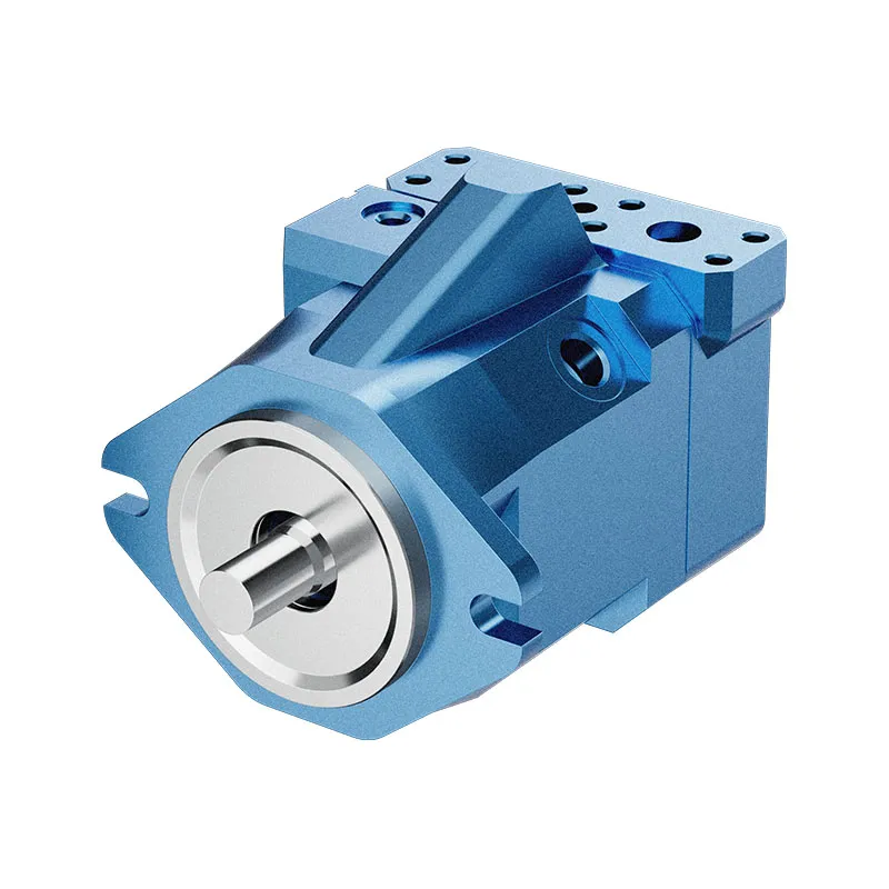
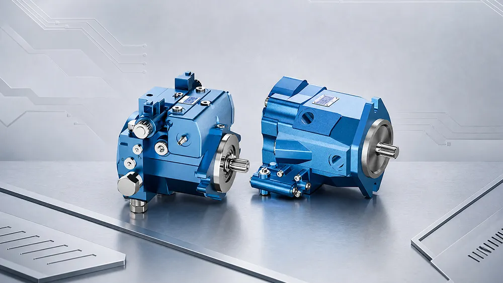
For a variable-flow product route, review the variable displacement piston pump A7VO after those data are complete. This is not a recommendation for a particular size or configuration; matching Prance technical documentation and RFQ review must confirm the final choice. Submit the inputs through the contact page.
FAQs
How do you select hydraulic pump displacement?
Start with required theoretical flow and actual pump-shaft speed, then calculate a first-pass displacement. Validate it against pressure, drive torque or power, inlet condition, fluid, mounting and control requirements.
How do you calculate pump displacement from flow and rpm?
With Q in L/min and n in rpm, use Vg = (Q × 1000) / n. The output is cm³/rev and remains a theoretical value until model-specific losses and limits are checked.
Does a larger displacement pump always give more flow?
At the same shaft speed, a larger displacement produces more theoretical flow. Actual delivered flow and acceptable operation still depend on the selected pump, speed, pressure, fluid and inlet conditions.
How do pressure and torque affect pump displacement selection?
Higher pressure raises the drive torque requirement for a given displacement. Confirm the prime mover, PTO, gearbox and selected pump can meet the intended continuous and peak duty.
Should mobile equipment use fixed or variable displacement?
Choose from the required flow-control behavior and duty cycle. Fixed and variable architectures offer different control paths, while the exact range and control options require model-specific documentation.
What information is needed to quote a mobile hydraulic pump?
Provide flow, actual pump speed, drive ratio, pressure duty, drive limits, fluid, inlet arrangement, mounting, shaft, rotation and control requirements.