Wenzhou Prance Hydraulic Equipment Co., Ltd

Efficiency and reliability advances in gear pump design for mobile hydraulics
When a mobile equipment OEM engineer in Des Moines, Iowa, encountered rising internal leakage and declining pump efficiency on a loader platform, he reviewed an online sizing guide, collected three quotations, and approved a replacement based on displacement, maximum pressure, and purchase price.
Within 160 operating hours, the loader cycle had slowed, oil temperature had increased by 14 deg C, and two machines required unplanned service. The maintenance team initially blamed defective pumps. A system review revealed a different cause: the pump had been selected without validating hot-oil viscosity, pressure duration, inlet restriction, contamination level, and coupling alignment.
The pump itself was not the only problem. The underlying selection method was incomplete.
Summary: A hydraulic gear pump achieves dependable mobile performance when displacement, speed, pressure, viscosity, inlet conditions, contamination, internal clearances, and mechanical interfaces are validated together. Under ISO 4409 testing, a 40 cm3/rev pump operating at 1,800 rpm produces 72 L/min theoretically. If measured flow is 65 L/min, volumetric efficiency is 90.3 percent. Improving overall efficiency from 82 percent to 86 percent at 25 kW hydraulic output reduces required shaft input by approximately 1.42 kW. OEM buyers should therefore request multi-point performance curves, pressure-duration ratings, cleanliness limits, endurance evidence, and traceable inspection records.
What is a gear pump, and how does a gear pump hydraulic system work?
A gear pump is a positive-displacement pump that transports hydraulic fluid through the spaces between rotating gear teeth and the surrounding housing.
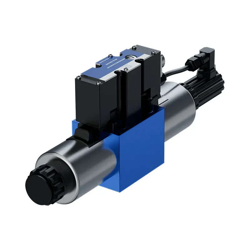
As the gears separate near the inlet, increasing volume draws fluid into the pump. The rotating gears carry the fluid around the housing before the meshing teeth force it toward the outlet.
Theoretical flow can be calculated as follows:
Theoretical flow in L/min = displacement in cm3/rev x speed in rpm / 1,000
A 40 cm3/rev pump operating at 1,800 rpm therefore has a theoretical flow of 72 L/min. Actual outlet flow is lower because some oil moves through internal clearances rather than reaching the machine actuators.
The working principle explains where pump losses originate
Gear pump losses fall into two principal categories:
- Volumetric losses reduce delivered flow. Oil leaks across gear tips, side faces, bearing regions, and the gear-mesh transition.
- Mechanical losses increase input torque. Bearings, seals, fluid shear, gear contact, and pressure forces consume shaft power.
Volumetric efficiency is calculated as:
Volumetric efficiency = actual flow / theoretical flow x 100 percent
If theoretical flow is 72 L/min and measured flow is 65 L/min, volumetric efficiency is 90.3 percent.
ISO 4409:2019 provides methods for determining and presenting the steady-state performance of positive-displacement pumps. A credible test should record flow, pressure, rotational speed, fluid temperature, and input torque.
Gear pump hydraulic performance depends on the complete operating envelope
A single rated-flow figure cannot predict performance across a mobile machine’s duty cycle. The engineering evaluation should cover:
- Minimum, rated, and maximum speeds
- Low, medium, and rated pressures
- Cold-start and stabilized oil temperatures
- Continuous, intermittent, and peak-pressure conditions
- Initial and post-endurance performance
- Approved fluid types and viscosity ranges
Internal leakage becomes particularly important at low speed because it represents a larger percentage of theoretical flow. A 3 L/min loss may appear acceptable when theoretical flow is 75 L/min, but the same loss becomes critical when theoretical flow falls to 20 L/min.
The National Fluid Power Association’s 2025 Industrial Technology Roadmap identifies efficiency, reliability, durability, power density, environmental impact, and serviceability as important fluid-power development priorities. Although the roadmap focuses on industrial applications, the same requirements are increasingly relevant to construction, agricultural, mining, and material-handling equipment.
Hydraulic pump gear design advances target leakage, heat, and premature wear
Modern pump development concentrates on maintaining effective sealing without creating excessive friction. The objective is not to eliminate all internal clearance, which would prevent lubrication and thermal expansion, but to control the clearance throughout the operating range.
Efficiency enhancements begin with pressure balance and controlled clearances
Current design improvements commonly include:
- Pressure-balanced side plates that maintain gear-face sealing
- Refined port timing that reduces trapped-volume compression
- Optimized tooth profiles that improve load distribution
- Stiffer housings that limit pressure-related deflection
- Improved bearing support that stabilizes the rotating gears
- Controlled surface finishes that support lubrication and sealing
The hydraulic pump gear profile affects pulsation, noise, trapped volume, contact stress, and leakage. However, ISO 4409 does not prescribe one universal clearance or efficiency value. Each design must be supported by repeatable performance testing.
At 250 bar, a leakage loss of 2 L/min represents approximately 0.83 kW of lost hydraulic power:
Power loss in kW = pressure in bar x leakage in L/min / 600
This energy becomes heat instead of productive actuator output.
Reliability and durability advances depend on fluid and inlet control
A correctly manufactured pump can still fail early when the oil is contaminated, aerated, excessively cold, excessively hot, or restricted at the inlet.
The most important controls include:
- Keeping viscosity within the manufacturer’s approved operating range
- Defining a measurable ISO 4406 cleanliness target
- Selecting filters using recognized test evidence such as ISO 16889
- Providing sufficient inlet flow during cold starts and high-speed operation
- Preventing suction-line restrictions, foaming, and air ingestion
For example, a 40 cm3/rev pump at 1,800 rpm requires 72 L/min theoretically. If the inlet can supply only 90 percent of that demand, the 7.2 L/min deficit may contribute to cavitation, aeration, noise, and surface damage.
Gear pump advantages and disadvantages should be evaluated together
| Design characteristic | Advantage | Disadvantage or tradeoff |
|---|---|---|
| Fixed displacement | Predictable theoretical flow | Excess flow may be throttled and converted into heat |
| Compact construction | High power density | Internal-clearance changes can affect leakage |
| Limited component count | Competitive cost and straightforward service | Fewer control options than variable-displacement pumps |
| Robust operating principle | Suitable for demanding mobile applications | Pressure ripple and noise may be higher |
| Broad speed capability | Compatible with many engine-driven machines | Inlet performance becomes critical at high speed |
| Relative contamination tolerance | Often more tolerant than precision piston designs | Contamination still accelerates bearing and housing wear |
The principal advantage is not immunity to operating conditions. It is the ability to deliver compact, economical, and reliable hydraulic power when those conditions are properly controlled.
A hydraulic gear pump delivers more value when performance is verified across the duty cycle
The following comparison presents procurement controls rather than universal product guarantees. Final acceptance limits should be agreed between the OEM and supplier.
| Decision factor | Nominal selection | Engineering-controlled selection | Business effect |
| Performance evidence | One rated-flow value | ISO 4409 map across pressure, speed, and temperature | More accurate cycle-time prediction |
| Efficiency | One best-point figure | Volumetric, mechanical, and overall efficiency curves | Lower heat and energy demand |
| Pressure capability | One maximum-pressure number | Continuous, intermittent, and peak ratings with time limits | Lower fatigue risk |
| Leakage | No hot-oil limit | Maximum leakage at defined viscosity and temperature | Reduced flow deterioration |
| Endurance | Short functional test | Buyer-defined duty cycle followed by repeat performance testing | Evidence of efficiency retention |
| Cleanliness | General instruction to use clean oil | ISO 4406 target with filtration and flushing plan | Lower abrasive-wear exposure |
| Compatibility | Similar flange and shaft dimensions | Interface, coupling, port, seal, and fluid review | Fewer installation changes |
| Traceability | Basic product label | Batch, material, inspection, and test records | Faster failure analysis |
| Commercial evaluation | Lowest initial price | Energy, maintenance, downtime, and secondary damage | More realistic total cost |
For a system delivering an average hydraulic output of 25 kW:
- At 82 percent overall efficiency, required shaft input is 30.49 kW.
- At 86 percent overall efficiency, required shaft input is 29.07 kW.
- The difference is approximately 1.42 kW.
- Across 2,000 hours, the difference equals approximately 2.84 MWh of mechanical input before engine-efficiency corrections.
Downtime can create an even larger cost. If one failure stops a machine for six hours at USD 450 per hour, the operational loss is USD 2,700 before labor, replacement oil, transport, and secondary component damage are included.
Gear pump hydraulic requirements change across applications and operating regions
A responsible supplier cannot provide one universal price or performance level for every mobile application. Displacement, pressure capability, shaft design, port arrangement, testing depth, documentation, annual volume, and warranty requirements all affect the commercial position.
Application conditions define the appropriate performance level
| Region and application | Principal challenge | Recommended design priority | Relative cost position |
| U.S. Midwest agricultural and construction equipment | Cold starts, dust, seasonal workloads, repeated pressure cycles | Cold-inlet validation, contamination control, pressure-duration mapping | Medium |
| Northern European municipal machinery | Low temperatures, noise expectations, extensive documentation | Cold-viscosity behavior, ripple control, conformity records | Medium to high |
| Middle Eastern construction equipment | Heat, dust, and sustained loading | Hot-oil efficiency, seal compatibility, cooling margin | Medium to high |
| Southeast Asian compact machinery | Heat, humidity, and variable maintenance quality | Filtration, corrosion protection, simple service access | Value to medium |
| Global high-duty OEM platforms | Multiple climates, large production volume, warranty exposure | Broad performance maps, endurance testing, configuration control | Higher development cost |
A standard-duty configuration may suit intermittent material handling. A high-duty configuration may justify stronger bearing support, improved pressure balance, broader validation, and more detailed production traceability.
Original engineering visuals strengthen technical credibility
Suitable original visuals for this article include:
- A real test-bench photograph with the alt text: “Gear pump efficiency testing under controlled pressure, speed, and oil temperature.”
- An original leakage-path diagram with the alt text: “Internal leakage paths across gear tips, side plates, and the gear mesh.”
- A Midwest loader field photograph with the alt text: “Mobile loader operating in the U.S. Midwest.”
- A performance graph with the alt text: “Gear pump volumetric efficiency at different pressures and temperatures.”
Repeated stock photographs should be avoided because they provide little evidence of engineering experience or product traceability.
Hydraulic pump gear selection must follow relevant performance and safety standards
| Standard or conformity framework | Practical relevance | Risk if misunderstood |
| ISO 4409:2019 | Pump performance and efficiency testing | Supplier curves cannot be compared reliably |
| ISO 4413:2010 | Safety requirements for hydraulic systems and components | Unsafe pressure control or installation |
| ISO 3019-1:2001 | Mounting-flange and shaft-end dimensions | Mechanical incompatibility and rework |
| ISO 4406:2021 | Solid-particle contamination coding | Ambiguous cleanliness requirements |
| ISO 16889 | Multi-pass hydraulic filter testing | Incorrect filter selection |
| ISO 9001:2015 | Quality-management and process controls | Weak traceability and change control |
| IEC 60204-1 | Electrical equipment for machinery | Safety gaps in electrohydraulic assemblies |
| IEC 60529 | Enclosure protection classifications | Inadequate dust or water protection |
| CE conformity framework | EU machinery conformity documentation | Invalid declarations or market-access delays |
| SGS inspection or testing | Independent evidence within a defined scope | Misuse of a report as universal certification |
A standalone pump is not automatically required to carry CE marking simply because it will be installed in CE-marked machinery. The final machine manufacturer must determine the applicable conformity route.
In the European Union, Machinery Directive 2006/42/EC remains relevant until Machinery Regulation (EU) 2023/1230 becomes applicable on January 20, 2027.
SGS is a testing and inspection organization rather than a regulation. Buyers should verify the report number, tested model, sample date, test method, results, and scope before relying on an SGS document.
OEMs should select a hydraulic gear pump through a controlled engineering process
- Performance curves should reflect real operating points.
OEM engineers should request flow, torque, and efficiency evidence under hot-oil, low-speed, and rated-pressure conditions. - Peak pressure should be treated as a time-based event.
A pressure rating without duration and cycle frequency cannot support a meaningful fatigue assessment. - Cleanliness should become a measurable requirement.
The ISO 4406 target, filter performance, flushing method, sampling location, and inspection frequency should be documented. - Documentation should be approved before pilot production.
Drawings, materials, test plans, inspection records, traceability, change control, and packaging requirements should be agreed before sample approval.
Prance Hydraulic provides mobile and industrial gear pump configurations with ISO 9001 quality-management certification, CE-related documentation where applicable, and SGS testing or inspection evidence within the agreed report scope.
OEM engineers can compare associated products through the hydraulic product center and review system integration through the company’s hydraulic solutions resources.
A complete gear pump hydraulic specification should include the machine schematic, target flow, pressure profile, speed range, fluid data, environmental conditions, interface drawing, annual volume, validation requirements, and expected service life.
Buyers often ask these practical questions about mobile gear pump performance
What causes a mobile gear pump to lose efficiency?
The most common causes are increased internal clearance, low hot-oil viscosity, abrasive wear, excessive pressure, aeration, cavitation, and operation outside the approved speed range. Flow should be compared under the same pressure, speed, viscosity, and temperature before wear is diagnosed.
How is gear pump efficiency calculated?
Volumetric efficiency is actual flow divided by theoretical flow. Mechanical efficiency compares theoretical torque with actual input torque. Overall efficiency combines the volumetric and mechanical results.
Which oil viscosity is suitable for a gear pump?
There is no universal best viscosity. The correct requirement is the manufacturer’s approved viscosity range at cold start, normal temperature, and maximum operating temperature.
What causes hydraulic pump gear noise?
Hydraulic pump gear noise may result from inlet restriction, cavitation, aeration, trapped-volume compression, pressure ripple, coupling misalignment, bearing damage, or machine-structure resonance. The pump should not be replaced until pressure, inlet condition, vibration, and temperature have been checked.
How can mobile gear pump service life be extended?
Service life improves when pressure, speed, viscosity, cleanliness, inlet pressure, shaft alignment, and operating temperature remain within approved limits. Trend monitoring can reveal gradual performance loss before machine output becomes unacceptable.
Authoritative references support the engineering recommendations in this article.
- National Fluid Power Association: 2025 Industrial Technology Roadmap
- ISO 4409:2019: Methods of testing and presenting steady-state performance
- ISO 4413:2010: General rules and safety requirements for hydraulic systems
- ISO 3019-1:2001: Dimensions for mounting flanges and shaft ends
- Fluid Power World: A designer’s guide to hydraulic pumps
Better mobile performance follows measurable engineering decisions
A pump does not become dependable because its nameplate shows sufficient pressure. It becomes dependable when leakage, heat, contamination, interfaces, pressure duration, and maintenance conditions have been converted into measurable limits.
Prance Hydraulic builds mobile hydraulic components and system-ready gear pump solutions for that decision point. Explore the Prance Hydraulic gear pump product range and contact the engineering team with the target flow, pressure profile, fluid specification, machine duty cycle, and required service life for a configuration review.