Wenzhou Prance Hydraulic Equipment Co., Ltd

Gerotor vs Geroller Motor: Low-Speed Hydraulic Drive Selection
Gerotor vs geroller motor comparison focuses on the orbiting displacement set inside a low-speed high-torque hydraulic motor. A gerotor set uses direct sliding contact between an externally lobed inner star and an internally lobed outer ring. A geroler—also commonly spelled Geroler in industry—adds rollers around the outer ring contact positions, changing sliding contact toward rolling contact. The roller design can improve mechanical efficiency, starting behavior, low-speed smoothness, and durability under demanding load, but the complete motor still determines the rating. Displacement, valve timing, shaft and bearing design, case pressure, pressure differential, speed, duty cycle, and circuit protection matter more than the name alone.
Shared orbital motor principle
The inner star has one fewer lobe than the surrounding outer geometry and runs on an eccentric path. As hydraulic oil is directed into selected chambers, pressure acts on the changing chamber areas and causes the star to orbit. A coupling converts orbital movement into concentric output-shaft rotation. A distributor valve repeatedly connects expanding chambers to the low-pressure side and contracting or driven chambers to the high-pressure side, depending on motor direction.
Because the displacement set encloses a relatively large volume per shaft revolution, orbital motors can produce useful torque at low speed without a separate reduction gearbox in many applications. They are positive-displacement motors: theoretical speed follows flow divided by displacement, while theoretical torque follows pressure differential and displacement. Leakage and friction reduce actual performance.
What is a gerotor motor?
In a gerotor set, the profiles of the inner star and outer ring contact directly. The chambers between them expand and contract as the star orbits. The mechanism is compact and economical, making it suitable for many light- and medium-duty low-speed drives. Direct contact means sliding and contact stress must be managed by geometry, surface finish, fluid film, material, and operating limits.
The general gerotor geometry is also used in pumps. An open research review from Universitat Politècnica de Catalunya covers gerotor technology in pumps and orbital motors, including geometry, modeling, and performance research. Purdue University’s Maha Fluid Power Research Center also lists peer-reviewed work on gerotors and hydraulic orbit-motor efficiency.
What is a geroller motor?
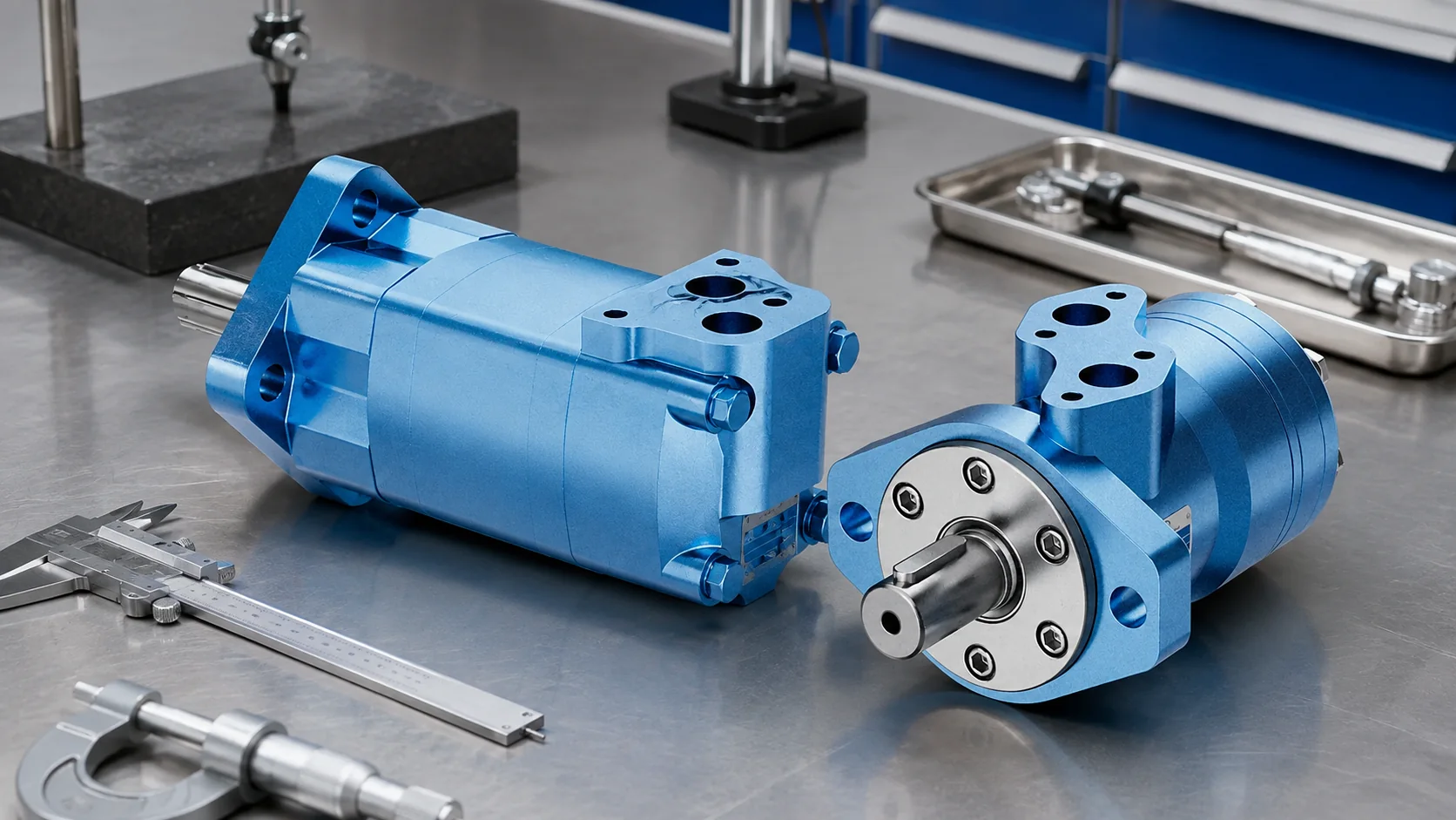
A geroller set places cylindrical rollers in the outer ring positions. The inner star works against those rollers as it orbits. Rolling elements reduce sliding at that interface and can improve efficiency and wear behavior, particularly at higher loads or low speeds. The added parts and tighter manufacturing demands usually make the displacement set more complex.
Rollers do not eliminate friction or leakage. The distributor, coupling, shaft bearings, seals, end clearances, and housing still contribute loss. A geroller set also cannot compensate for an incorrect circuit, inadequate return path, excessive case pressure, side loading, or contaminated oil.
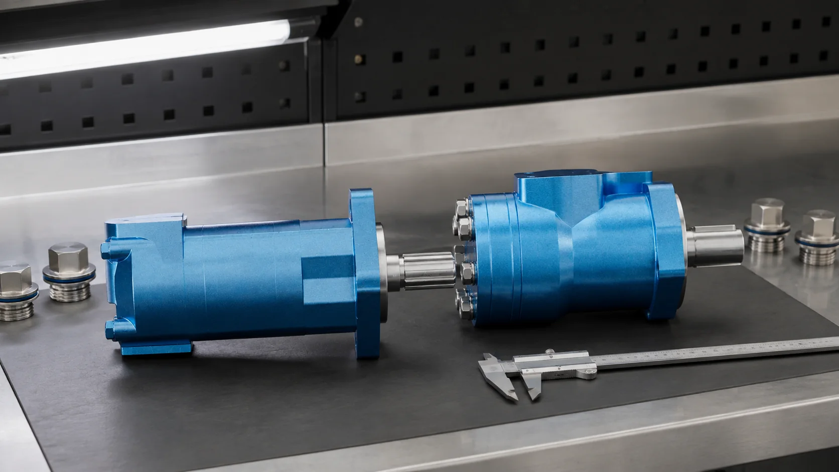
Gerotor and geroller comparison
| Decision factor | Gerotor motor | Geroller motor | Evidence to request |
|---|---|---|---|
| Outer contact | Direct sliding profile contact | Cylindrical rollers at outer contact positions | Section drawing and series description |
| Complexity | Simpler displacement set | Additional precision rollers | Parts and service documentation |
| Low-speed behavior | Suitable within series limits | Often selected for smoother demanding duty | Minimum stable speed and efficiency curves |
| Load capability | Depends on complete motor design | Often offered for heavier duty | Continuous/intermittent pressure and torque |
| Cost | Often lower | Often higher due to added geometry | Total installed and lifecycle cost |
| Failure sensitivity | Wear at direct profiles and clearances | Roller, profile, clearance, and timing condition | Cleanliness and inspection limits |
Torque, speed, and displacement
Theoretical motor speed is flow divided by displacement, using consistent units. Actual speed is lower because some supply flow leaks internally. Theoretical torque is proportional to pressure differential multiplied by displacement and divided by a rotational constant. Actual output torque is lower because mechanical friction consumes part of the input.
Do not size from theoretical equations alone. Starting torque, minimum stable speed, mechanical and volumetric efficiency, allowable back pressure, pressure peaks, brake release demand, and thermal duty can dominate the selection. Review the complete speed-torque and efficiency data at the intended oil viscosity and temperature. Our related article explains hydraulic motor torque and speed evidence.
Starting torque and very-low-speed operation
Static friction, distributor transition, seal drag, load variation, and chamber pressure balance influence starting torque. A machine that needs to restart under load may require more than the continuous running torque calculation. Ask for starting torque data and define the lowest operating speed, load inertia, expected stop position, and required direction changes.
At very low speed, leakage and individual displacement events become more visible. Output may exhibit speed ripple even when average rpm is correct. A geroller mechanism can help, but valve timing and complete motor construction remain important. If precise low-speed motion is required, record allowable speed variation and validate the motor with the actual control valve and load.
Pressure differential, return pressure, and case drain
Motor torque responds to the pressure difference between inlet and outlet, not inlet pressure alone. A restrictive return line, downstream valve, series-connected motor, or braking circuit raises outlet pressure and reduces useful differential for a given supply pressure. It can also increase seal and housing loads.
Some orbital motors drain internal leakage through a low-pressure main port; others require or permit a dedicated case drain under defined conditions. Shaft-seal capability and allowable case pressure vary. Never plug, add, or reroute a drain based on another series. Confirm whether the motor may operate in series, with closed-center braking, or under high return pressure.
Bearing loads and application mechanics
The displacement set produces torque, but the output shaft and bearings must also support external loads. Wheel drives, chain sprockets, pulleys, augers, and couplings create different radial and axial forces. Overhung load depends on magnitude, direction, and distance from the mounting face. A motor with adequate hydraulic torque can still fail if its bearing arrangement is unsuitable.
Provide sprocket or pulley pitch diameter, chain or belt tension, wheel offset, coupling type, axial load, mounting orientation, and shock condition. If an external bearing or gearbox supports the load, define alignment and coupling movement. Do not use the motor shaft as a structural axle unless the series is rated for that duty.
Circuit protection and braking
Inertia can drive a hydraulic motor after the directional valve shifts. A load can also overrun the motor on a slope or lowering function. Cross-port relief valves, anti-cavitation checks, counterbalance or brake valves, charge supply, and mechanical brakes may be needed. The correct arrangement depends on whether the load is resisting, overrunning, reversible, or safety critical.
A closed valve can trap expanding oil as temperature changes, and abrupt reversal can create pressure spikes. Circuit protection must be designed around the machine dynamics, not added from a generic diagram. OSHA’s warning about unsafe hydraulic system modifications illustrates why raising pressure or changing components requires a complete engineering review.
Contamination and failure evidence
Particles can score distributor surfaces, damage the star and ring profiles, mark rollers, and increase internal leakage. Oil that is too thin, overheated, aerated, or incompatible can weaken lubrication. A motor that slows under load may have insufficient flow, excessive leakage, high return pressure, brake drag, control-valve loss, or an overloaded mechanism.
Record inlet and outlet pressure, flow, oil temperature, speed, commanded valve position, case or drain flow, load condition, and noise. Inspect the filter and oil before opening the motor. Keep component orientation and timing evidence. Replacing only the displacement set without correcting contaminated oil or circuit transients risks recurrence.
Selection and RFQ checklist
- Gerotor or geroller preference and duty reason
- Displacement and target speed across flow range
- Running, starting, peak, and stall torque requirements
- Continuous and transient pressure differential
- Return pressure, series operation, and case-drain arrangement
- Reversing frequency, overrunning load, and braking method
- Shaft, flange, ports, rotation, and installation envelope
- Radial, axial, and overhung loads with dimensions
- Fluid, viscosity, temperature, cleanliness, and ambient conditions
- Existing model code, circuit, duty cycle, and failure evidence
Review Prance Hydraulic’s orbital motor family and broader hydraulic motor overview. Complementary checks include LSHT motor selection, motor case-drain review, and motor RFQ inputs.
Educational video: gerotor chamber motion

Watch the gerotor principle on YouTube. The chamber animation helps explain geometry but does not specify a motor’s load rating.
FAQ
Is Geroler the same as geroller?
Geroler is a widely used industry spelling and trade-derived term; geroller is a descriptive spelling. Both commonly refer to an orbital set with rollers in the outer ring.
Does a geroller motor always make more torque?
Not automatically. Torque depends on displacement, pressure differential, efficiency, and complete motor limits. Roller contact may improve performance under demanding conditions.
Which motor is better at very low speed?
Geroller designs are often selected for smoother heavy-duty low-speed operation, but compare minimum stable speed, ripple, starting torque, and control-valve performance.
Can an orbital motor hold a suspended load?
Internal leakage means the motor alone should not be treated as a load-holding device. Use an engineered brake or load-control circuit appropriate to the hazard.
Why does an orbital motor run slowly under load?
Possible causes include inadequate supply flow, internal leakage, high return pressure, valve loss, brake drag, unsuitable displacement, or excessive mechanical load.