Wenzhou Prance Hydraulic Equipment Co., Ltd

Hydraulic Motor Speed Measurement: Tachometers, Pulses, and Test Records
Hydraulic motor speed measurement establishes the actual shaft speed under a defined operating condition. It complements a flow-and-displacement calculation but does not replace it. An optical tachometer, encoder or suitable proximity sensor can measure rotation; the correct choice depends on access, speed range, required response and installation safety. A reliable result also records load, fluid temperature, pressure, sampling method and instrument uncertainty. This guide explains how to choose a measurement method, convert pulses to rpm and interpret a speed record without mistaking a display setting or theoretical flow estimate for actual motor performance.
Define the speed quantity before selecting a sensor
The motor shaft, gearbox output and driven drum can rotate at different speeds. Specify the location that matters to the engineering question. If the objective is to verify motor delivery, measure the motor shaft or use a verified transmission ratio. If the objective is conveyor travel, the final drive and belt behaviour may be more relevant than the motor alone.
A variable-displacement motor can change speed while the pump flow stays similar. A gearbox ratio, belt slip or coupling problem can also change the relationship between motor and machine movement. Record the mechanical path so the technician does not compare a drum tachometer reading directly with a motor calculation.
Define whether you need average running speed, startup acceleration, low-speed stability or a transient maximum. A handheld instrument reporting a slowly updated average may be suitable for a steady operating check but inadequate for a short overspeed event. The measurement method must match the timescale of the question.
Non-contact optical tachometers
An optical tachometer detects a repeatable mark or reflection as the shaft rotates. For a simple arrangement, one approved reflective target produces one pulse per revolution. Extra reflective surfaces, repeated patterns or an incorrect instrument setting can cause the instrument to count multiple events and display an erroneous speed.
The target must be placed with the machine isolated and in a position that remains securely attached. Never remove guarding merely to obtain a convenient line of sight during operation. Use a protected inspection window or a properly engineered measurement arrangement. Follow the instrument and equipment instructions for distance, alignment and permissible access.
Surface condition and background light affect optical detection. Oil mist, dirt, a loose mark or vibration can cause lost or false pulses. Confirm signal quality using an approved repeat reading or an independent method where the result is critical. A stable numerical display alone does not prove correct counting.
Encoders and proximity sensors
An encoder can provide multiple pulses per revolution and, where designed for it, direction information. Higher pulse density can improve low-speed resolution, but the counter and acquisition equipment must support the resulting frequency at maximum speed. An unsuitable input may miss pulses or saturate even when the sensor is functioning.
A proximity sensor can detect teeth or another suitable rotating target. The number of detectable features per revolution must be known. The target material, sensing distance, runout and mounting stiffness affect detection. Do not drill, weld or attach an improvised target to a motor shaft without an approved mechanical design.
Electrical compatibility also matters. Confirm sensor supply, output type, signal levels, cable requirements and counter input. An encoder's nominal pulses per revolution may be different from the counts produced by a controller that counts several edges or uses quadrature decoding. State the effective counts per revolution used in the calculation.
Convert a pulse record to rpm
For a known effective count N per revolution and measured count frequency f in counts per second, rpm = 60f / N. The word effective matters: if the sensor produces 100 pulse cycles per revolution but the controller counts four edges for each cycle, the corresponding calculation uses 400 counts per revolution for that count-frequency signal.
As an illustrative example, a verified system with 60 effective counts per revolution reports 120 counts per second. Speed is 60 × 120 / 60 = 120 rpm. These values are teaching inputs, not a specification for a Prance motor or encoder. A factor-of-two or factor-of-four discrepancy is often a reason to review edge counting before investigating a hydraulic fault.
For a measurement based on total counts C during a gate time t, rpm = 60C / (Nt). At low speed, a short gate may contain few counts, creating coarse resolution. A longer gate improves count resolution but averages away faster changes. Period measurement between pulses offers another approach, although timing resolution, missing pulses and irregular rotation still require attention.
Choose the method for the task
| Measurement task | Suitable starting method | Main limitation to check |
|---|---|---|
| Steady shaft-speed confirmation | Protected optical tachometer measurement | Target counting and accessible line of sight |
| Continuous machine monitoring | Approved encoder or proximity pickup | Input frequency, mounting and environmental suitability |
| Low-speed stability | Pulse timing or higher-resolution encoder | Sparse pulses and averaging that hides variation |
| Startup and stop behaviour | Time-synchronised acquisition | Sensor response and recording interval |
| Gearbox output verification | Output sensor plus known transmission data | Slip, ratio definition and different measurement locations |
Supporting technical context: NPTEL: hydraulic motor operation, NIST: identifying measurement uncertainty. Illustrative calculations and qualitative checks do not establish a product rating or universal acceptance limit.
This qualitative table does not recommend a universal pulse density or sampling rate. Select those values from the speed range, dynamics and instrument specifications. Measurement uncertainty principles support documenting both random variation and other sources of error.
Compare measured speed with expected speed
For a hydraulic motor with displacement Vg in cubic centimetres per revolution and inlet flow Q in litres per minute, ideal speed is 1,000Q / Vg rpm. Actual speed depends on the relevant volumetric behaviour and operating conditions. Ensure the flow measurement represents motor inlet flow and that displacement corresponds to the current motor setting.
Suppose the theoretical calculation predicts 500 rpm but the tachometer reports 450 rpm. Before assigning the entire difference to motor leakage, check shaft speed location, flow-meter accuracy, actual displacement, bypass branches and instrument settings. A speed calculation based on pump outlet flow may include flow that never reaches the motor.
Record pressure difference across the motor and temperature at the same time. Outlet back pressure affects conditions, and viscosity changes can influence leakage. Comparing a cold no-load speed with a hot loaded speed without documenting the differences can create a misleading conclusion about deterioration.
Capture low-speed irregularity properly
A slowly changing average can conceal stick-slip or cyclic variation. If the concern is smooth rotation at low speed, retain time-stamped samples or pulse intervals rather than only a final average. Establish a consistent definition for minimum, maximum and mean speed over a stated observation interval.
The sensor can itself create apparent irregularity. Uneven target spacing, shaft runout or missed pulses may produce a periodic timing pattern. Correlate the signal with a known reference or inspect the target under isolation. An observed fluctuation is evidence to investigate; it is not automatically proof of hydraulic torque ripple.
For a test involving a load, document the load and mechanical friction. Gearbox backlash, a sticky bearing or an intermittent machine contact can affect motion. Record pressure and speed together where practical, using a common time base. This helps separate hydraulic events from mechanical disturbances without relying on memory of what happened during the test.
Instrument uncertainty and calibration
Instrument accuracy, resolution and repeatability describe different things. Accuracy specifications may be stated as a percentage of reading, a fixed count term or another form. Read the specification for the operating range and measurement mode. A display with many digits does not guarantee a correspondingly small uncertainty.
Document calibration status and any correction used. Include uncertainty from target counts, timing, alignment and the operating process where relevant. Repeating the measurement helps assess variation but does not reveal every systematic error. A tachometer consistently counting two targets can repeat the same wrong number very well.
For a procurement acceptance test, agree how uncertainty affects the decision. If a result lies near a contractual limit, the measurement method and decision rule matter. Do not round away the difference or silently change the averaging interval until a result appears acceptable. Preserve the raw record and explain the method used.
Product and enquiry requirements
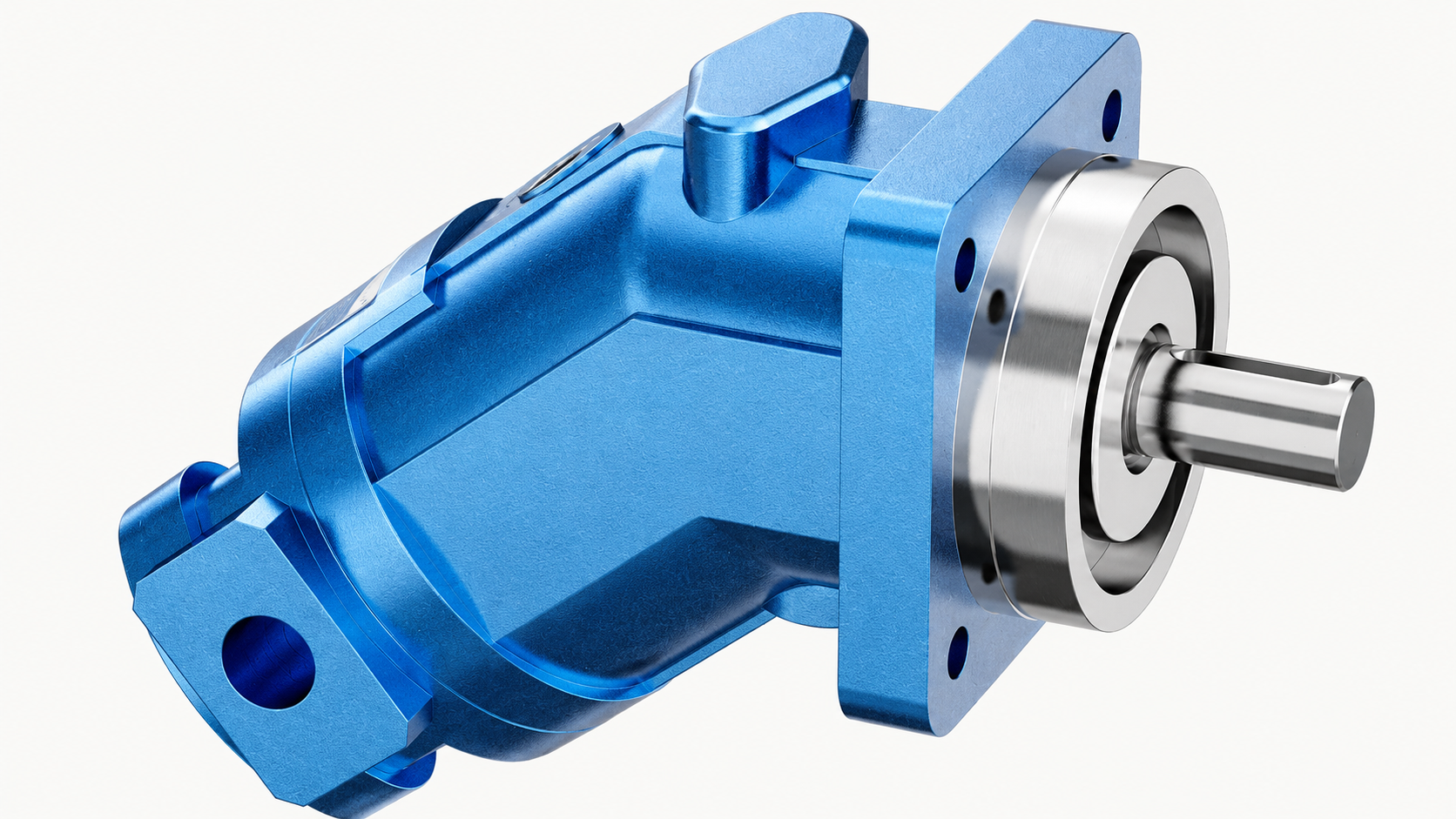
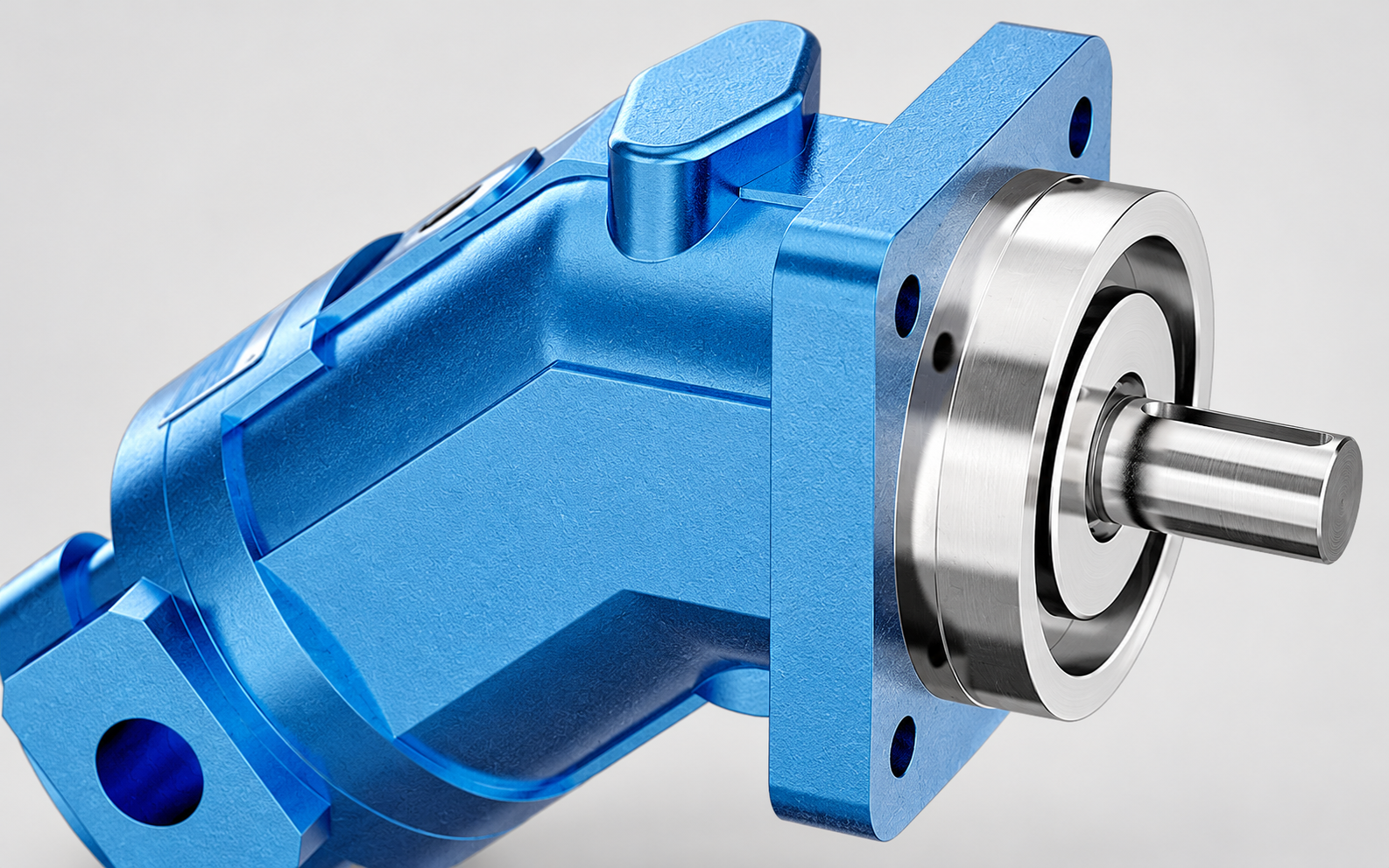
Prance lists the A2FM fixed-displacement axial piston motor as a relevant family for shaft-speed enquiries. Its exterior illustration shows the housing, flange and shaft arrangement. It does not establish that an encoder mount, speed pickup or particular sensor is fitted or available. Ask for the exact ordered drawing and approved measurement interface.
Provide the intended speed range, duty, load and installation layout. State whether the sensor is for temporary testing or permanent control. If the measurement is used for overspeed protection, the equipment designer must define the protection architecture and required reliability separately from this measurement guide.
For a replacement motor, preserve any existing feedback interface specification. A hydraulically similar motor with a different mechanical sensor arrangement can require changes to mounting, wiring or control scaling. Verify the complete feedback path rather than assuming a motor displacement match also guarantees a speed-feedback match.
Frequently asked questions
Can I use pump flow to report actual motor rpm?
It gives an estimate only after accounting for motor inlet flow, actual displacement and operating behaviour. For actual shaft speed, use a verified rotational measurement method and record its conditions.
Why is the encoder speed four times the expected value?
Review the effective counts per revolution and edge-counting mode. Quadrature decoding can multiply the count rate relative to the nominal pulse cycles. Correct the scaling before interpreting the discrepancy as a motor fault.
Is a handheld tachometer suitable for low-speed stability testing?
It may be adequate for a mean-speed check but may hide short fluctuations through averaging. Verify update rate and resolution. A pulse timing record or approved higher-resolution encoder may better answer a stability question.
Does a very stable display prove the measurement is accurate?
No. A repeated wrong target count or incorrect scaling can produce a stable incorrect display. Check the measurement location, counting definition and instrument setup, and use an independent verification where needed.
Can I mount a speed sensor on any hydraulic motor?
Not without checking the mechanical and environmental arrangement. Confirm a suitable target and approved mounting method. The catalogue exterior alone does not establish a sensor interface or permission to modify a shaft.
Related products and engineering guides
Fixed Displacement Motor A2FM, related hydraulic product range, Hydraulic Motor Speed Calculation From Flow and Displacement, Hydraulic Motor Efficiency Calculation: Volumetric, Mechanical, and Overall, Hydraulic Motor Drain Flow Test: Measuring Internal Leakage. Provide the circuit, fluid, duty and exact ordered configuration when requesting component-specific data.
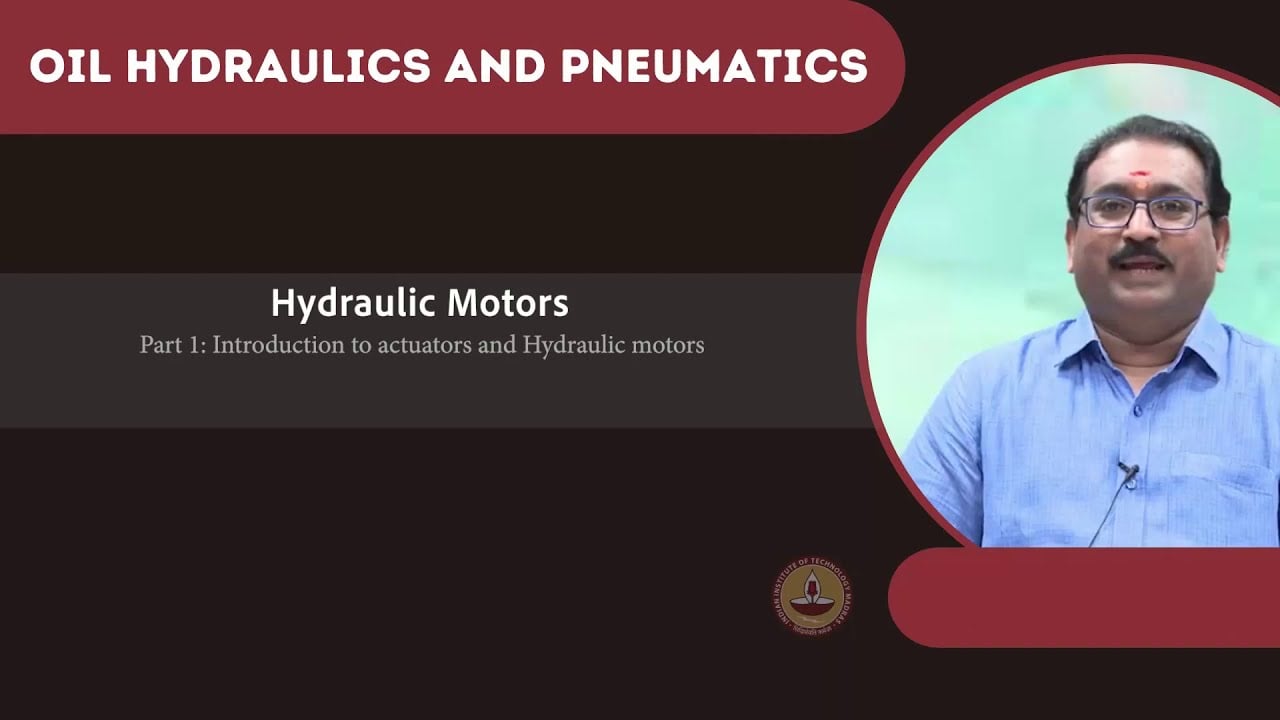
University lesson: 6.3 – Hydraulic Motors
This NPTEL university lecture explains the component principles underlying this guide; the lecture is background education rather than a configuration-specific test procedure.
Technical references
- NPTEL: hydraulic motor operation
- NIST: identifying measurement uncertainty
- NIOSH: hazardous-energy isolation
Sources support the stated principles and method scope. Illustrative inputs and another manufacturer’s documents do not establish Prance component ratings, warranties or brand affiliation.