Wenzhou Prance Hydraulic Equipment Co., Ltd

Hydraulic Motor Back Pressure: Limits, Effects, and Testing
Hydraulic motor back pressure is the pressure at the motor outlet that opposes return flow. Some back pressure is normal in closed circuits, braking arrangements and long return lines, but it reduces the pressure difference available to make torque. Excessive outlet or case pressure can increase heat, reduce efficiency, overload shaft seals and damage motors that require a separate low-pressure case drain.
This guide is written for engineers, maintenance teams and equipment buyers who need a defensible decision rather than a generic definition. It explains the working relationship, the measurements that matter, common failure interpretations and the records that should travel with a replacement request. Hydraulic systems store dangerous energy; isolate, depressurize and follow the machine manufacturer’s procedure before opening a line or removing a component.
What hydraulic motor back pressure means in a real circuit
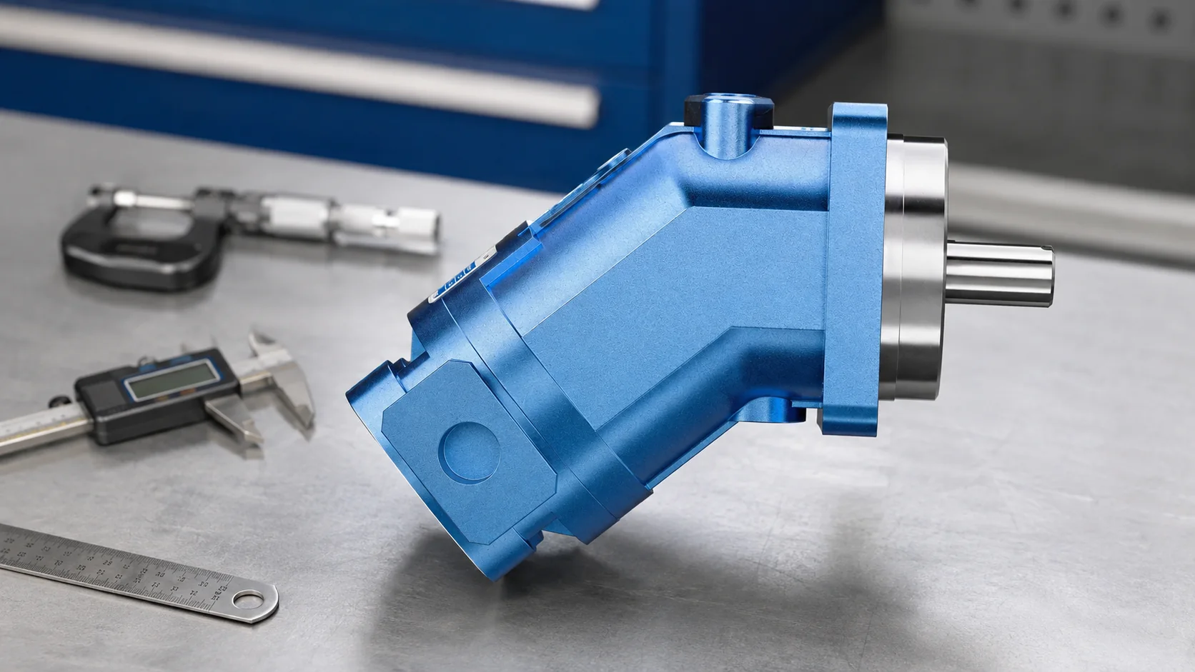
The relevant hardware includes motor inlet, outlet, case drain, return filter, cooler, directional valve and brake valve. Each item affects the result seen at the shaft or actuator. Pressure exists because the load resists flow, while flow determines motion rate. Leakage, restriction, compressibility and control response connect those quantities. That is why a component cannot be judged reliably on a bench description alone.
Acceptable pressure comes from the exact motor data, circuit type, speed, fluid and duration. Never assume the outlet rating equals the case-pressure or shaft-seal rating; these limits may differ substantially. Put these conditions in a duty table with normal, peak and standby states. Separate continuous ratings from intermittent peaks. Record whether values were calculated, measured or copied from a data sheet. This small discipline prevents an optimistic peak number from being treated as a sustainable operating point.
How the components work together
Oil follows the available pressure gradient, but the path is defined by clearances, port timing and valve state. When a control element moves, it changes an opening or a displacement and the system settles at a new balance of pump supply, load demand and losses. The transition matters as much as the final reading: acceleration, deceleration, rapid valve shifts and cold starts often create the highest stress.
The correct interpretation begins with a schematic and a time sequence. Mark the source, load, return and drain paths. For every machine step, note which ports are connected, which volume can be trapped and where make-up oil can enter. Then compare that logic with the installed hoses. A surprising number of apparent component failures are caused by a port option, plumbing change or control state that does not match the drawing.
| Item to verify | Why it matters | Useful evidence |
|---|---|---|
| motor inlet | Function and interface | Drawing or model code |
| outlet | Wear or restriction | Inspection photo and measurement |
| case drain | Pressure and leakage | Hot and cold test result |
| return filter | Compatibility and orientation | Manufacturer service data |
| cooler | Cleanliness and surface condition | Oil and filter evidence |
| directional valve and brake valve | Recorded limit | Commissioning record |
Selection and sizing workflow
Begin with the load. Convert the required force or torque and speed into pressure difference and flow, then add realistic allowances for efficiency and line losses. Check the complete operating envelope rather than selecting from a single nominal point. The prime mover must support the highest simultaneous hydraulic power, and the reservoir, cooler and filtration must handle the expected loss power.
Next, verify interfaces: shaft and mounting geometry, port size and thread, rotation, drain arrangement, electrical command, connector and environmental protection. Similar-looking components can have different internal options. Never infer displacement, spool function, pressure setting or rotation from appearance. Preserve the full nameplate and model code, and request a controlled drawing when interchangeability is important.
Finally, agree on acceptance criteria. Useful criteria include measured flow or speed at stated pressure and temperature, external leakage, case or drain flow, noise observations, response time and stable control. A procurement comparison that lists only unit price leaves the most expensive risks—installation changes, commissioning time and repeat failure—outside the decision.
Symptoms and what they do not prove
Common observations include weak torque, hot return line, seal leakage, rising case drain, erratic speed and failures after a cold start. None proves a single root cause. For example, heat can come from internal leakage, relief flow, throttling, excessive return pressure or unsuitable viscosity. Noise may be aeration, cavitation, mechanical contact or control oscillation. A failed seal may be the victim of case pressure or misalignment rather than the initiating fault.
Use a cause-and-evidence matrix. Put each plausible mechanism in one column and the reading that would support or contradict it in another. Test the safest, easiest distinctions first. Keep time-aligned readings where possible because a peak that lasts 200 milliseconds may disappear on a slow analog gauge while still stressing the component.
A safe diagnostic sequence
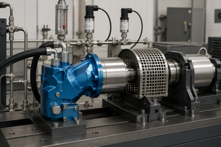
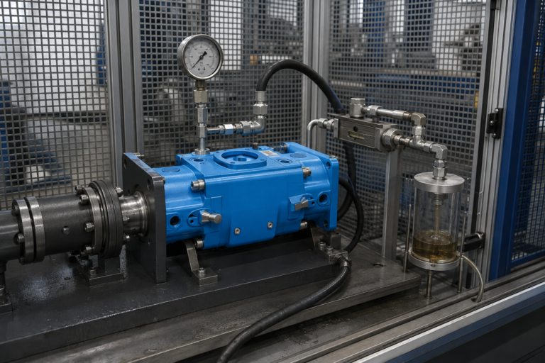
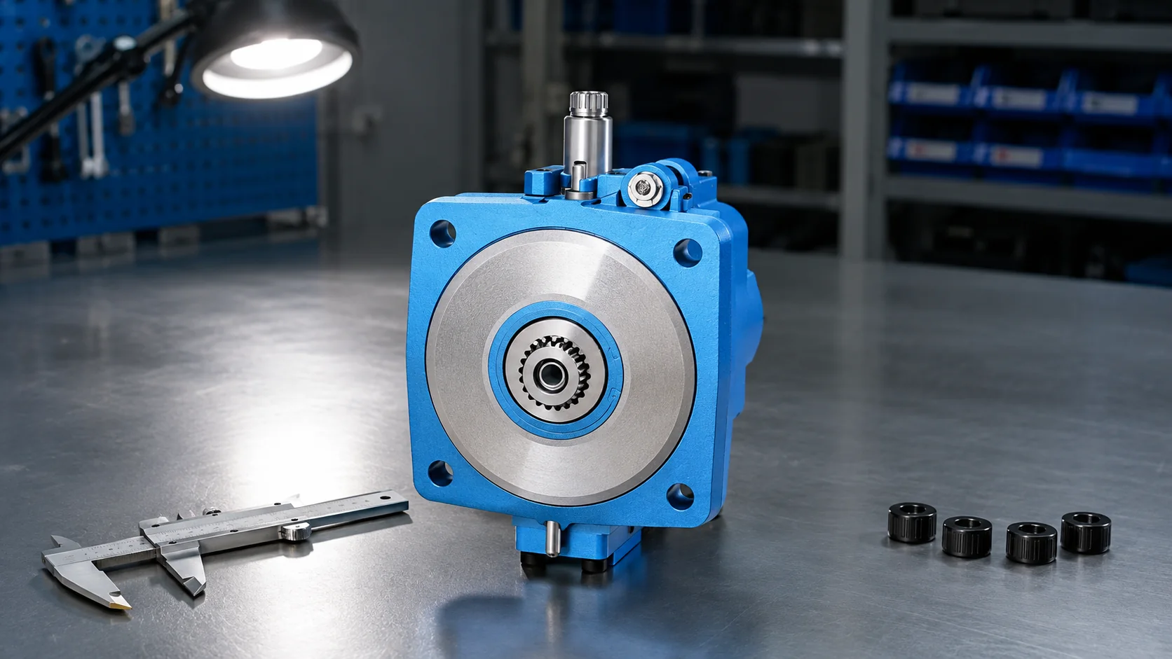
Install gauges at inlet, outlet and case drain, measure at operating temperature and peak deceleration, inspect return restrictions and quick couplers, then compare differential pressure and case pressure with documented limits. Use instruments with suitable pressure, temperature and fluid compatibility ratings. Install test points before the trial where practical, route hoses away from personnel and rotating parts, and never search for a pinhole leak with a hand.
Run a baseline at low risk, then reproduce the duty gradually. Capture standby, no-load motion, normal load and the most demanding transition. Note oil temperature because viscosity changes both leakage and pressure loss. If the result changes as the machine warms, that is diagnostic evidence, not an inconvenience to average away.
After testing, compare readings with component and system limits. Separate pump pressure from pressure difference across the motor or valve. Separate motor outlet pressure from case pressure. Separate commanded current from actual spool position. These distinctions prevent a healthy component from being blamed for a measurement taken at the wrong point.
Installation and commissioning controls
Cleanliness during installation is part of reliability. Cap open lines, clean the work area, use compatible seals and lubricants, and flush contaminated circuits according to an approved plan. Pre-fill or prime components where the manufacturer requires it. Confirm shaft alignment and coupling freedom before applying power. A dry or misaligned first start can erase the value of a careful selection.
Start with pressure limited and load reduced. Verify rotation and flow direction immediately. Watch inlet condition, outlet pressure, case drain, leakage, temperature and sound. Stop if readings move rapidly toward a limit. Increase duty in controlled steps and retain the commissioning record as the reference for future troubleshooting.
Procurement and replacement checklist
- Complete manufacturer, series and model code
- Clear nameplate, port and mounting photographs
- Machine schematic and hose routing
- Normal, peak and standby pressure and flow
- Fluid type, viscosity grade and temperature range
- Speed, torque or actuator duty over time
- Return and case-drain pressure limits
- Contamination and filter evidence
- Failure description and retained damaged parts
- Required test report, drawing and traceability
For component options, review Prance Hydraulic’s motors range and the broader hydraulic product overview. Related technical reading: system behavior guide and diagnostic guide. These links help connect the informational question to a reviewable product specification without treating the article as a substitute for application engineering.
Educational video

References
- OSHA: Hydraulic Systems Modification Safety
- Indiana DWD: Fundamentals of Fluid Power—Hydraulics
- Purdue Maha Fluid Power Research
Practical conclusion
The best decision is the one that remains correct across the machine’s full duty cycle and can be verified after installation. Keep the schematic, measurements, model-code interpretation and commissioning results together. That evidence shortens future troubleshooting, improves supplier communication and makes a repeat failure less likely.
Frequently asked questions
What is the first specification to verify?
Start with the exact component model and the machine duty. Then verify pressure, flow, fluid, temperature, mounting, porting and control limits against the manufacturer documentation.
Can this issue be diagnosed from one pressure gauge?
No. Install gauges at inlet, outlet and case drain, measure at operating temperature and peak deceleration, inspect return restrictions and quick couplers, then compare differential pressure and case pressure with documented limits. A single steady reading can hide transient and return-side conditions.
Should an adjustment be made before testing?
No. Record the original setting, isolate stored energy, use rated instruments and follow the equipment service procedure. An undocumented adjustment can mask the cause or create a hazard.
What should an RFQ include?
Include model code, photos, schematic, operating cycle, measured pressures and flows, fluid and temperature, failure history, dimensional interfaces and the required verification documents.