Wenzhou Prance Hydraulic Equipment Co., Ltd

Pump Inlet Boosting: When a Booster Solves More Than a Larger Suction Line
A hydraulic pump inlet boost system adds pressure upstream of the main pump; a larger suction line only reduces pressure lost on the way there. Choose between them by measuring the inlet pressure available at the required speed, oil temperature, and reservoir level. Hydraulic pump anti cavitation inlet boost is useful when an approved inlet-pressure requirement cannot be met by reducing avoidable suction losses alone. It is not a substitute for repairing air leaks or clearing a blocked inlet. The pump’s maximum permitted inlet and housing pressures still apply, so adding more boost without checking those limits can create another failure.
Two remedies with different jobs
Imagine the reservoir as the starting point of a pressure budget. Atmospheric pressure, any approved reservoir pressurization, and the height of oil above the pump contribute to the available pressure. Pipe friction, fittings, strainers, and acceleration of the oil consume part of that budget. A wider, shorter, less restrictive line conserves pressure. It does not supply energy beyond the reservoir conditions.
A booster supplies additional energy before oil reaches the main pump. Depending on the approved design, that function may be provided by a separate pump or an integrated inlet stage. The system then has another operating condition to control: enough boost throughout the required flow range, without exceeding component limits during low flow, starting, or shutdown. Those duties make boosting a system design decision rather than an accessory chosen from a noise symptom.
Establish whether the problem is actually inlet starvation
Noise alone cannot distinguish vapor cavitation, released dissolved air, entrained external air, mechanical vibration, or an outlet-side restriction. Record the main pump inlet pressure at a manufacturer-approved measurement location, together with speed, delivered flow, oil temperature, reservoir level, and operating state. Use absolute pressure for comparison with an absolute-pressure limit. A vacuum gauge reading must be converted using the local atmospheric pressure rather than silently compared with a different reference.
If the symptom appears only after a hose replacement, check the new hose’s internal diameter, vacuum suitability, liner condition, bend radius, and fittings. A nominally matching connection can hide a narrower bore. If the symptom follows a fluid change, establish viscosity at the actual starting temperature. If it follows a speed increase, the original suction arrangement may no longer provide the required filling conditions. These observations narrow the investigation before a booster is considered.
Build a pressure budget before buying hardware
For a preliminary steady-flow review, write the pressure at the pump inlet as reservoir surface absolute pressure plus static elevation contribution, minus line and local losses. Add an approved boost contribution only when that equipment is present. Keep every term in the same pressure units. This accounting is an engineering estimate, not a replacement for the pump manufacturer’s inlet requirement or a detailed transient model.
For an illustrative example only, suppose the reservoir provides 1.00 bar absolute, elevation contributes 0.05 bar, and the complete inlet path loses 0.25 bar at the chosen operating point. The estimated inlet pressure is 0.80 bar absolute. Reducing losses to 0.10 bar would raise it to 0.95 bar absolute. Whether either condition is acceptable depends on the particular pump, speed, displacement, and fluid. These figures are invented calculation inputs, not A2FO ratings or recommended setpoints.
The calculation also explains why a bigger pipe can solve one installation but not another. Where friction dominates, recovering that lost pressure may be enough. Where local atmospheric pressure, mounting height, or internal filling requirements dominate, further enlargement has diminishing value. The design must then change the available supply conditions, reduce demand, or use an approved boost arrangement.
Compare the practical options
| Observed condition | First design question | Likely useful action | What still needs verification |
|---|---|---|---|
| Pressure falls across a restrictive inlet assembly | Is the restriction necessary and correctly sized? | Reduce verified losses using approved components | Cold-oil pressure drop and contamination requirements |
| Adequate inlet conditions at low speed but not high speed | Does the pump require increased inlet pressure at that speed? | Review speed limit, line losses, and approved boosting | Full operating envelope, not one warm test |
| Air enters through a connection | Where is the air path? | Repair the connection and verify sealing | Repeat measurements after repair |
| Minimum reservoir level makes the symptom worse | Is static head or air ingestion changing? | Correct reservoir arrangement or operating level | Slosh, slope, return placement, and minimum usable volume |
| Boost pressure rises when main-pump demand falls | How is excess supply controlled? | Engineer an approved regulating or bypass arrangement | Maximum inlet, housing, and seal pressure |
This decision table combines pressure accounting with diagnostic recommendations. It does not assign universal inlet-pressure limits. The DOE pumping-system sourcebook and NPTEL suction-head lesson explain the influence of supply conditions and pressure losses on cavitation. Their general pump principles do not establish an axial-piston-pump inlet rating or an A2FO specification.
Cold oil changes the answer
An inlet that works at normal operating temperature may perform poorly after an overnight cold soak. Higher viscosity increases resistance through the same passages. A warm test therefore cannot prove that the inlet remains adequate on the coldest permitted start. Record the fluid grade, its viscosity-temperature information, the coldest component temperature, and the manufacturer’s starting restrictions.
Increasing speed to make the oil warm faster can increase the demand that the inlet is already failing to meet. Use the equipment manufacturer’s warm-up method and operating restrictions. A heater, an approved circulation arrangement, or a different approved fluid may be more appropriate than changing the main inlet hardware. Confirm fluid compatibility and the full hot operating range before substituting a thinner oil.
What a booster adds to the design
A separate booster must supply the required inlet flow over the main pump’s operating range. Include leakage, bypass flow, and other connected demands where the particular circuit requires them. Its pressure regulation must work when the main pump consumes little flow as well as when demand is highest. Check how the booster starts, whether the main pump can turn before supply is established, and what happens if the booster stops.
Do not assume that an inlet connection can accept the main system’s working pressure. The approved maximum may be constrained by shaft sealing, housing conditions, internal passages, or the manufacturer’s design. Return-line-fed arrangements also need their own analysis: return flow can disappear or change direction during parts of the cycle, and heated or aerated return oil is not automatically a suitable inlet supply. A circuit drawing and model-specific review are required.
Check the A2FO connection without inferring specifications
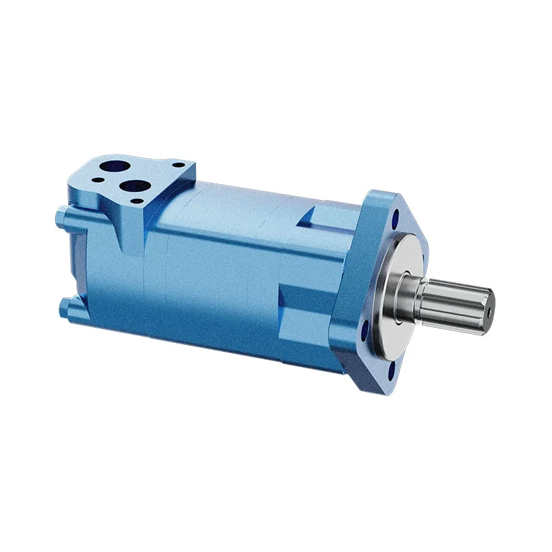
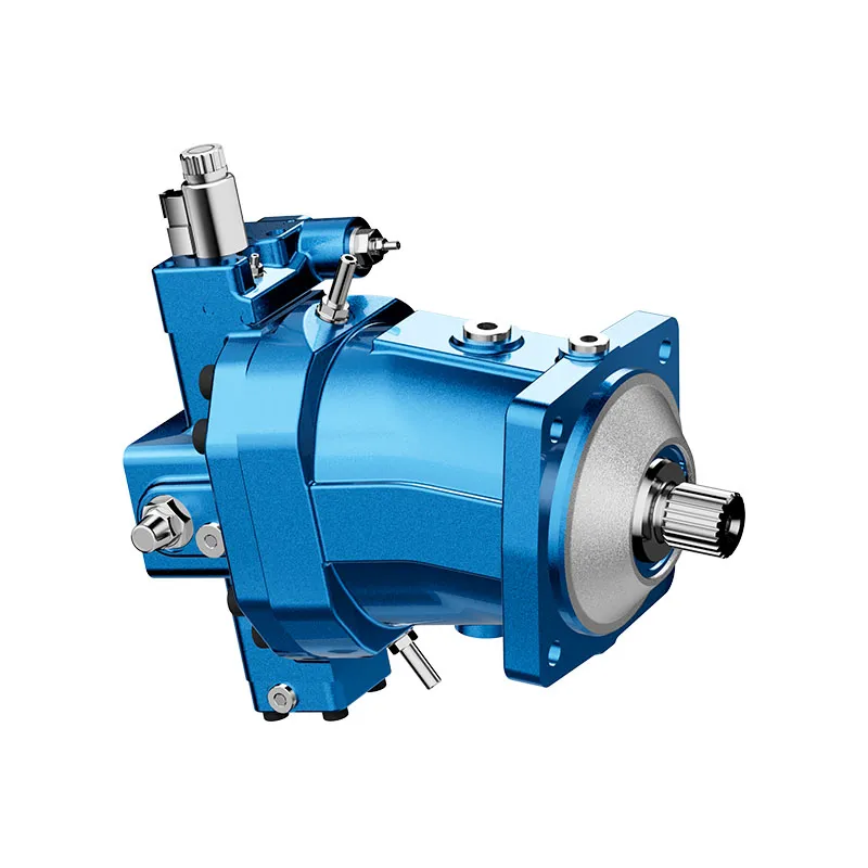
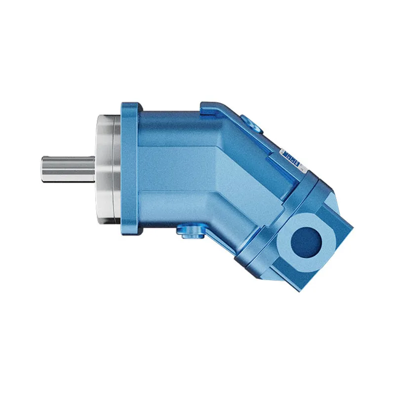
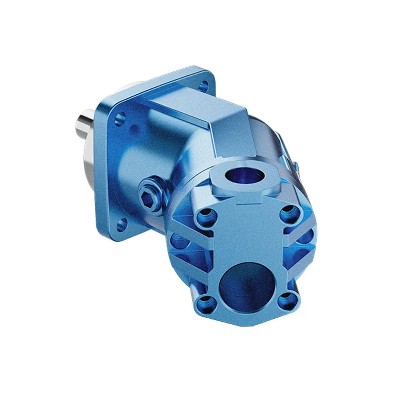
The A2FO Series axial piston fixed-displacement pump is a relevant product family for an inlet-condition discussion because pump filling must be considered alongside pressure and speed selection. Its original exterior photographs identify the product offered on the website. They do not demonstrate an integral boost stage, a particular inlet-pressure rating, or permission to pressurize a reservoir.
Before requesting a pump or reviewing an existing installation, provide the complete ordering code, displacement, rotation direction, operating speed range, fluid, minimum and maximum temperatures, measured inlet pressure, and reservoir arrangement. Request the documentation applicable to that exact configuration. A generic axial-piston-pump chart or a different manufacturer’s boost recommendation cannot be transferred to this product as a specification.
Validate the complete operating cycle
Agree acceptance conditions before modification. Include the coldest permitted start, minimum reservoir level, maximum required flow, the transition from idle to demand, and shutdown. Use suitable instrumentation and approved test points. The goal is to demonstrate that the inlet remains within its documented envelope while outlet performance and housing conditions also remain acceptable.
Inspecting or modifying hydraulic plumbing requires isolation, release of stored pressure, and protection against unexpected movement. Do not loosen a fitting to admit oil or air while the pump is running. Do not intentionally force cavitation to locate a threshold unless the manufacturer provides a controlled test procedure. Stop on abnormal noise, unstable pressure, excessive temperature, or any documented limit being approached.
A successful change should remain effective on repeated cycles, not just during a short workshop run with warm oil and a full tank. Preserve before-and-after measurements so a future filter, hose, or fluid substitution can be evaluated against the accepted configuration.
Questions to settle in the quotation
Ask whether boosting is required, optional, or prohibited for the exact operating envelope. Request the allowed inlet-pressure range and the measurement reference, starting restrictions, housing and drain requirements, and compatibility of any proposed booster. Identify the lowest supply pressure and the highest pressure that can occur during a bypass or low-demand state.
Also establish who is responsible for sizing the complete inlet path and approving the control sequence. Purchasing a suitable main pump does not by itself validate the surrounding installation. A quotation supported by the pressure budget, circuit drawing, and operating temperatures is more useful than a request for an unspecified “anti-cavitation pump.”
Frequently asked questions
Can a larger suction hose replace a boost pump?
It can when recoverable line losses are the reason inlet pressure falls below the documented requirement. It cannot raise available pressure beyond the reservoir supply conditions. Compare the improved pressure budget with the exact pump requirement before removing or omitting a booster.
Is positive inlet gauge pressure always better?
No. Both minimum and maximum permitted inlet conditions matter. Additional pressure can exceed the approved envelope or change housing and seal conditions. Use the particular pump documentation and an approved circuit rather than a universal positive-pressure target.
Does inlet boost cure aeration?
It does not repair an air leak, poor return arrangement, or inadequate reservoir deaeration. Increased pressure can change how a symptom appears while the source remains. Identify external air entry separately from vapor cavitation before selecting a remedy.
Should boost pressure be measured only at the booster outlet?
No. Pressure can fall between the booster and the main pump through pipes, fittings, or filters. Measure at the locations required by the equipment documentation and account for the pressure difference. The main pump’s actual inlet condition is the acceptance point.
Can the example pressure budget select an A2FO pump?
No. It demonstrates the difference between conserving pressure and adding pressure. Product selection requires configuration-specific limits, speed, displacement, fluid viscosity, and the actual installation. None of the illustrative pressures is a product rating.
Related product and engineering resources
A2FO Series Axial Piston Fixed Displacement Pump, hydraulic pump product range, Hydraulic Pump Aeration vs Cavitation: Symptoms and Test Methods, Hydraulic Pump Noise Isolation: Mounting and Pipe-Borne Paths. Confirm the complete product code and application requirements when requesting a configuration review.
Technical references
- US Department of Energy pumping-system sourcebook
- NPTEL suction head and cavitation
- NIOSH hazardous energy control
University lesson: hydraulic pump inlet conditions
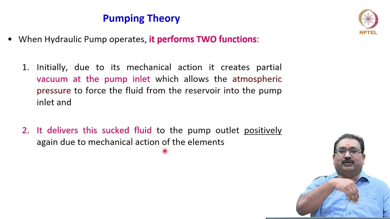
3.2 – Hydraulic Pumps by NPTEL-NOC IITM provides background on pump operating principles. It supplements the component fundamentals; it is not a test procedure for the complete circuit discussed above.