Wenzhou Prance Hydraulic Equipment Co., Ltd

Hydraulic Motor Coupling Selection: Misalignment and Torque Capacity
Hydraulic motor coupling selection must cover continuous torque, peak and reversing torque, shaft interfaces, rotational speed, alignment and environmental duty. A coupling that fits the shaft diameter is not necessarily suitable for the machine. Check the motor's permitted external loads as well as the coupling's ratings. Flexible elements can accommodate limited movement, but they must not be used to hide poor mounting or shaft alignment.
For a buyer, the useful result is a documented connection between the selected motor and driven equipment. This guide explains how to assemble that specification and how to verify the installed coupling without assigning a universal service factor or tolerance.
Start with the machine duty rather than the catalog bore
Describe what the motor drives, how it starts and whether the load can reverse or overrun. A conveyor operating steadily has a different duty from a winch, indexing mechanism or crusher experiencing shocks. Record normal speed, maximum speed, expected starts per hour and the time spent at each significant operating point.
Identify whether the coupling is intended only to transmit torque or also forms part of a supported shaft arrangement. A direct connection to a gearbox input needs a different interface review from a long adapter carrying a sprocket. Include emergency stops and blocked-load events where they are part of the designed duty. These conditions can dominate the coupling choice even when average power is modest.
Calculate the relevant torque values
When shaft power P is in kW and speed n is in rpm, torque T in N m is approximately 9550P/n. The equation relates mechanical shaft power to rotation; it does not establish a motor's available starting torque. At zero speed, the power equation cannot be used to derive stall torque by dividing by zero.
For an illustrative running point, 5 kW at 250 rpm corresponds to approximately 191 N m. Treat that as a calculation example rather than a rating for any Prance product. The selection must additionally cover startup, reversal and peak torque using motor performance data and the driven load's requirements. Do not convert hydraulic input power directly into shaft torque without accounting for the relevant losses.
Use pressure-derived motor torque with its limits
Theoretical motor torque is related to pressure difference and displacement. Actual delivered torque depends on mechanical efficiency and the operating condition. Breakaway behavior is not necessarily represented by the running efficiency value at a different speed. Use the selected motor's documented starting and running performance when specifying the coupling.
A relief setting can help bound a circuit condition, but transients and load-driven operation require their own review. An externally driven motor may generate pressure during braking. Ask the system designer which torque events the coupling must survive and which protective devices limit them. A coupling should not be selected from an average gauge reading when the machine repeatedly experiences short shocks.
Apply service factors as documented, not guessed
Coupling suppliers may use service factors to account for driven equipment, shocks, operating time or starts. Follow the selected supplier's method and definitions. A factor used for one coupling family may not have the same meaning for another. Stacking several informal factors can produce an oversized connection without resolving the actual duty uncertainty.
Keep a record of the torque basis and the chosen factor. If the machine duty is unclear, ask for engineering review rather than calling an arbitrary factor conservative. Confirm whether the rated torque is continuous, nominal, maximum or fatigue-related. The same printed number can represent different acceptance conditions across products.
Compare coupling behavior, not just torque capacity
Rigid couplings require closely controlled alignment and transmit movement into the surrounding supports. Flexible couplings offer limited accommodation and may provide damping, but their torsional stiffness, backlash and response depend on design. A control-sensitive drive can react differently after replacing one coupling type with another.
For frequent reversals or positioning, review lost motion and torsional behavior with the machine designer. For shock duty, review how the flexible element responds and how it is inspected. A coupling advertised as flexible is not a universal solution for high shock, excessive offset and precise positioning simultaneously. Select the characteristics that actually matter to the application.
Verify shaft and hub interfaces
Check shaft diameter or spline details, key dimensions, hub length and the approved engagement. A spline specification needs more than tooth count; fit, geometry and engagement must match. Keyed hubs require the correct shaft, key and hub arrangement. Do not force a near-fitting hub onto the motor shaft or modify a spline based on appearance.
Confirm the fastening method and installation instructions. Set screws, clamping hubs and interference fits have different requirements. Ask whether the hub may be heated and what temperature limits apply to nearby seals or bearings. Pressing a hub in a way that transfers force through the motor bearings can damage the assembly before first startup.
Review alignment and axial freedom together
Measure parallel offset, angular error and the axial spacing specified for the selected coupling. A connection can be well centered but axially bottomed, producing thrust as temperature changes or supports move. Check how each machine shaft is located and whether the coupling is allowed to transmit axial force.
Follow the tighter applicable motor and coupling requirement. Check the mounting before alignment, including bracket flatness and bolt seating. Recheck after final tightening and after hose loads are applied. Where thermal movement is significant, use a documented cold alignment target and operating check rather than assuming the room-temperature reading represents the running condition.
Use a specification table for quotation comparisons
| Selection item | Information to send | Supplier confirmation required |
|---|---|---|
| Running torque | Shaft power and speed or documented motor output | Suitable continuous capacity at the actual duty |
| Peak duty | Startup, reversal, braking and shock events | Applicable peak or fatigue basis |
| Shaft interface | Complete keyed, splined or other shaft drawing | Matching hub, fit and engagement |
| Alignment | Expected angular, parallel and axial movement | Permitted limits for the selected configuration |
| Speed | Normal, maximum and any overspeed condition | Speed rating and balance requirements |
| Environment | Temperature, fluid exposure, dust and corrosion | Suitable materials and maintenance requirements |
Complete this table before comparing price. Two quotations that use different torque definitions or hub assumptions are not equivalent offers.
Check loads imposed on the motor
A coupling can impose reaction forces when misaligned and may constrain axial movement. Confirm that these forces remain within the motor's external-load capability. If the coupling connects to a poorly supported or flexible structure, the alignment measured during installation may change as the machine runs.
Consider support stiffness, bracket deflection and the position of external bearings. A coupling should not become an unintended bearing or a device that pulls two shafts into line. When additional support is required, have the complete load path reviewed. Adding a bearing without checking axial location and thermal movement can create a new constraint.
Guard the assembly and maintain access
Provide a guard appropriate to the machine's rotating components and operating environment. Preserve inspection and maintenance access through an approved arrangement. A coupling that fits mechanically but prevents safe tightening, lubrication or inspection can be a poor practical choice. Review removal space before accepting an installed location.
Keep hoses and wiring clear of rotating parts and consider how a failed flexible element would affect the driven machine. Identify whether loss of torque transmission creates a load-holding risk. A motor coupling is not a substitute for the brake or safety function required by the application. Those functions must remain effective under the designed failure scenarios.
Commission with recorded operating conditions
Check hub positioning, fastening, alignment and guard installation with energy isolated. Confirm the motor rotation direction and brake release before demanding full torque. Begin with the approved low-risk commissioning sequence, then approach the actual speed and load in controlled stages. Watch for vibration, abnormal heating, loose fasteners or unexpected control response.
Record the operating point and observations so later maintenance has a useful baseline. If symptoms appear only during reversal, capture command, speed and pressure together. Stop and investigate rather than tightening components repeatedly without finding the cause. Repeated loosening can indicate a fit, alignment or duty mismatch that torque on the fastener alone will not fix.
Specify replacement and inspection requirements
For a replaceable flexible element, identify the exact part and the supplier's inspection criteria. Keep the hub and element combination consistent with the approved configuration. A visually similar element can have different stiffness, material or load capacity. Record any replacement that changes the coupling's behavior and assess whether the machine control response must be checked again.
Ask the supplier for installation instructions, tightening values, inspection points and removal requirements. Set maintenance intervals according to the actual duty and manufacturer guidance rather than inventing a universal schedule. Include the coupling record with the motor documentation so a future replacement order covers both interfaces.
Frequently asked questions
Can I select a coupling only from motor power?
No. Convert power and speed into running torque and separately consider starting, reversing and peak events. Shaft fit, speed, alignment and environmental requirements also matter.
Is a flexible coupling always better than a rigid coupling?
It depends on the machine. Flexibility, damping, backlash and stiffness have tradeoffs. Choose the behavior required by the drive rather than assuming one type is universally superior.
Can the coupling correct a misaligned mounting bracket?
No. It accommodates only the movement within its documented limits. Correct the mounting and align the shafts before relying on the coupling's allowable flexibility.
Why does a replacement coupling change reversal behavior?
Different torsional stiffness, damping or backlash can alter the response of the shaft system. Check those characteristics and repeat the relevant commissioning tests after a design change.
What should accompany a coupling quotation?
Request the exact hub and element configuration, rating basis, shaft-fit confirmation, installation instructions and alignment limits. The quotation should explicitly match the supplied motor and driven-shaft drawings.
Product and related engineering resources
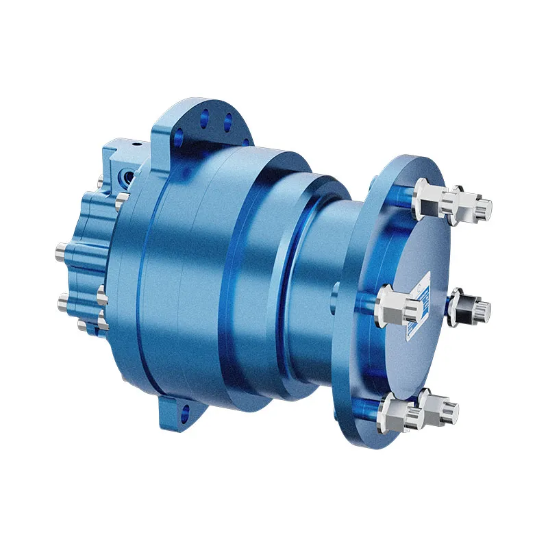
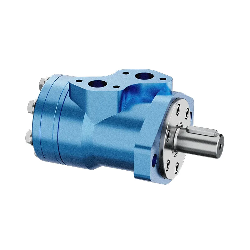
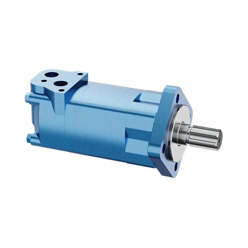
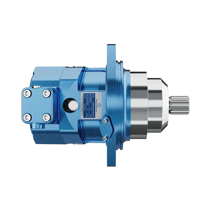
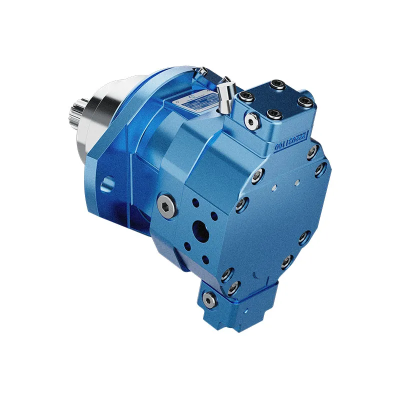
For a component enquiry, review Hydraulic Bent Fixed Displacement Piston Motor A6VE and provide the full specification and installation conditions. Related guides: piston motor range, orbital motor range, motor case-pressure checks, motor drain-flow measurement, motor efficiency calculation, Hydraulic Motor Shaft Load: Radial, Axial, and Overhung Limits, Hydraulic Motor Mounting Flanges and Shaft Standards Explained. Product photographs illustrate catalog configurations; they do not establish a pressure, speed or shaft-load rating for an unconfirmed order.
University lecture: hydraulic motor fundamentals
NPTEL-NOC IITM presents a hydraulic-motor lesson from IIT Madras. The lecture supports the distinction between hydraulic input and shaft output used in this guide. Component-specific installation and operating limits still require the selected motor documentation.

Open the NPTEL hydraulic motors lecture.
Technical and safety references
- NPTEL: Fundamentals of Industrial Oil Hydraulics and Pneumatics
- NIOSH: preventing injuries from hazardous energy
- Technical reference: orbital-motor operating principles and installation
These references provide educational and technical context. A reference manufacturer model-specific ratings are not specifications for a Prance product and do not imply brand affiliation or authorization.