Wenzhou Prance Hydraulic Equipment Co., Ltd

Hydraulic Motor Mounting Flanges and Shaft Standards Explained
Hydraulic motor flange and shaft standards help describe mechanical interfaces, but a standard designation alone does not prove that two motors are interchangeable. Compare the complete mounting and shaft drawing, including pilot, bolt pattern, shaft geometry, projection, engagement and reference dimensions. Hydraulic performance, drain arrangement and external-load limits must be checked separately.
This guide helps buyers read interface descriptions and prepare an installation comparison. It does not reproduce proprietary dimension tables or assign measurements to an unidentified model. Use the controlled drawing for the exact configuration being ordered.
Separate the mounting interface from the hydraulic connections
A mounting flange positions and supports the motor on the machine. Work ports connect the hydraulic circuit, and a shaft transfers torque to the driven equipment. All three interfaces can have standards associated with them, but they describe different features. A motor with a compatible port does not necessarily have a compatible mounting pilot or spline.
Prepare separate comparison sections for mounting, shaft and ports. Include drain and control connections in the hydraulic section. This prevents a quotation described as a standard motor from being accepted without identifying which features are actually standardized. A complete ordering code often contains options that change one interface while leaving the product family name unchanged.
Identify the standard and the exact variant
Common mounting and shaft descriptions refer to SAE or ISO arrangements. Obtain the full designation and the applicable drawing or revision. A shorthand label used in a sales conversation may omit bolt count, shaft option or a special mounting feature. Similar family labels should not be treated as identical dimensions.
Ask whether the offered interface conforms to a standard arrangement or is only described as similar. Modified pilots, special bolt patterns and extended shafts can be legitimate custom features, but they must be visible in the order specification. If a supplier cannot provide the controlled interface drawing, the fit remains unverified regardless of the familiar abbreviation in the product description.
Understand what the pilot does
The pilot or locating register establishes the motor's position relative to the mating structure. It should be evaluated together with the mating bore, reference face and specified fit. The mounting bolts generally secure the assembly; their holes should not be assumed to provide precise shaft alignment when the design relies on a pilot.
Check the pilot diameter, length, corner details and clearance to the machine bore. Paint, burrs or corrosion can prevent full seating even when nominal dimensions match. Do not use bolts to draw an interfering pilot into a bore without confirming the fit and assembly instructions. A partially seated flange can distort the motor and change alignment.
Read the complete bolt arrangement
Compare the bolt count, pattern, hole diameter, thread type where relevant and access for tightening. Include the fastener length and engagement required by the mating structure. A pattern that appears to line up can still leave insufficient seating area, inadequate thread engagement or interference with the housing.
Clarify whether holes are through holes or threaded and whether the machine uses metric or inch fasteners. Do not assume that a similar major diameter makes two thread systems interchangeable. Use the correct specified fasteners and tightening procedure. If an adapter plate is proposed, its stiffness, locating features and added shaft distance require review rather than being treated as a simple hole conversion.
Distinguish keyed shafts from splines
A keyed shaft requires matching diameter, key geometry, hub fit and engagement. A spline requires a complete geometry and fit description, not just tooth count. Pressure angle, pitch system, major and minor dimensions, tooth form and effective engagement can affect compatibility. A coupling that slides on is not proof of the intended torque-carrying fit.
Check whether the shaft is cylindrical, tapered, splined or supplied with a special end feature. Record thread or retaining details and the location of shoulders. If the replacement changes shaft type, review the whole hub arrangement and installation procedure. An improvised adapter can shift external loads or create insufficient engagement even when it connects the two parts physically.
Use reference faces consistently
Shaft projection must be measured from the same defined datum on both drawings. A dimension from the flange face is not automatically comparable to one from a shaft shoulder. Include hub engagement length, coupling gap, retaining features and space needed for installation and removal.
Check axial clearance after the motor is fully seated. A shaft can bottom inside a coupling or gearbox input before the flange reaches its mounting surface. Tightening the bolts in that condition can place unwanted thrust into the shaft system. Verify the assembled stack of dimensions rather than comparing one shaft-length number in isolation.
Create a form-and-fit comparison table
| Feature | Drawing information needed | Risk if omitted |
|---|---|---|
| Locating pilot | Diameter, length, reference face and fit | Poor seating or shaft misalignment |
| Mounting holes | Pattern, count, size and thread details | Wrong fasteners or incomplete attachment |
| Shaft geometry | Full keyed, splined or tapered designation | Incompatible hub or unreliable torque transfer |
| Shaft projection | Datum, shoulder position and usable engagement | Bottoming or insufficient hub contact |
| Housing envelope | Overall size, access and clearances | Interference with frame, hoses or guards |
| External loading | Force direction, location and permitted duty | Bearing or shaft overload despite a physical fit |
Use the table as an inspection checklist. Matching all listed dimensions establishes part of the mechanical review, not hydraulic performance or complete interchangeability.
Check housing orientation and service access
A mounting arrangement may permit several housing positions, but ports, drains and controls still need an approved orientation. Compare hose bend clearance, drain routing, connector access and guard space. A replacement that requires tight elbows or inaccessible fittings may create hydraulic restriction or maintenance problems.
Ensure that the nameplate and inspection points remain accessible. Consider how the motor will be supported while fasteners are installed and how it can be removed later. A physical fit that requires unsafe lifting or dismantling unrelated machinery may be unsuitable for the intended service even if the flange standard matches.
Consider what an adapter changes
An adapter plate or shaft adapter can resolve a dimensional difference, but it changes the assembled system. Additional axial distance can increase the moment from an overhung load. Added tolerances can affect concentricity, stiffness and alignment. The adapter also needs suitable materials, fasteners and load capacity for the machine.
Review the complete drawing stack and identify who accepts responsibility for the assembly. Do not call a motor a direct replacement when it depends on an unreviewed adapter. If a supplier offers an adapter as part of the package, request its controlled drawing, installation procedure and confirmation of the resulting shaft and bearing loads.
Keep standard interfaces separate from performance claims
A standardized flange or spline does not mean that two motors share displacement, pressure rating, speed capability, starting torque or drain requirements. A motor can install neatly and still run the machine too fast, overheat or expose its housing to excessive pressure. Perform the hydraulic and mechanical checks as separate but connected tasks.
For a replacement, compare the operating curves at the real duty and the allowed external shaft loading. Confirm rotation conventions and any brake or control options. Do not use a familiar flange designation to justify an unsupported brand-equivalence claim. The useful statement is that a documented configuration matches the defined application conditions.
Inspect the incoming motor before installation
Compare the nameplate and ordering code with the approved order. Inspect the pilot, flange face, shaft, ports and preservation plugs for damage. Use calibrated measurement tools and the specified datums for the dimensions selected in the acceptance plan. Avoid placing measuring jaws against delicate seal lips or forcing a hub onto the shaft as a substitute for measurement.
Record discrepancies before altering the component. Grinding a pilot, elongating holes or modifying a shaft can destroy the evidence needed to resolve an incorrect supply. If a dimension is outside the agreed drawing, keep the motor in a safe uninstalled condition and obtain a corrected supply or approved engineered change.
Commission the final assembly
Confirm complete flange seating, correct fasteners, coupling position and alignment. Check that installation has not introduced axial restraint or excessive external loading. Restore the required oil fill, drain route and work-port connections. Verify rotation at reduced risk using the approved commissioning sequence.
Then check the motor under the actual duty, including leakage, temperature and pressure behavior. Retain the mechanical measurements and operating acceptance record together. If a later motor uses a revised interface option, compare it with this complete record rather than copying an old order description without review.
Information to include in an interface RFQ
Send the existing motor code, machine mating drawing, shaft or coupling drawing and clear photographs with the viewing direction identified. State the relevant mounting and shaft designations in full and list any custom features. Include external loads, available space and whether an adapter is allowed.
Request a marked comparison drawing from the proposed supplier. It should identify matched features, differences and unresolved dimensions. Ask for shaft-fit and load confirmations alongside hydraulic performance data. A concise comparison document is more useful than a broad assurance that the motor uses an industry-standard interface.
Frequently asked questions
Does the same flange standard guarantee interchangeability?
No. Compare the exact interface variant and the shaft, housing, ports, loading and hydraulic performance. A common mounting designation resolves only part of the selection.
Is tooth count enough to identify a spline?
No. The spline geometry, pitch system, fit and engagement are also required. Obtain the full designation and mating-hub information rather than relying on a photograph.
Can bolt holes be enlarged to fit a replacement motor?
Do not modify the mounting without an approved engineering review. The pilot, strength, alignment and load path may still be incompatible after the holes are changed.
Why does the flange fit but the shaft not engage correctly?
Shaft type, projection, datum or usable engagement may differ. Compare the complete assembled dimension stack, including the coupling or gearbox input.
What evidence should a supplier provide?
A controlled configuration drawing, full ordering code, interface comparison and confirmation of the defined operating and external-load conditions. Familiar abbreviations alone are insufficient.
Product and related engineering resources
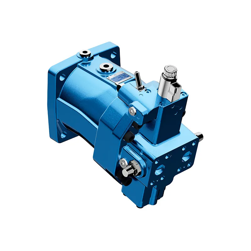
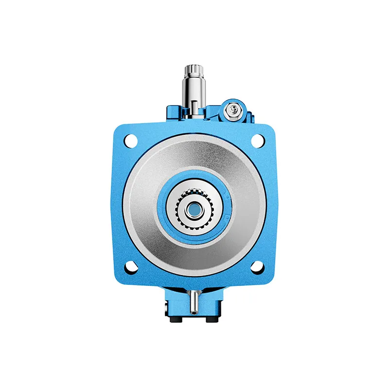
For a component enquiry, review Hydraulic High Pressure Piston Motor A6VM and provide the full specification and installation conditions. Related guides: piston motor range, orbital motor range, motor case-pressure checks, motor drain-flow measurement, motor efficiency calculation, Hydraulic Motor Coupling Selection: Misalignment and Torque Capacity, Hydraulic Motor Port Types: SAE, BSPP, NPT, and Metric. Product photographs illustrate catalog configurations; they do not establish a pressure, speed or shaft-load rating for an unconfirmed order.
University lecture: hydraulic motor fundamentals
NPTEL-NOC IITM presents a hydraulic-motor lesson from IIT Madras. The lecture supports the distinction between hydraulic input and shaft output used in this guide. Component-specific installation and operating limits still require the selected motor documentation.

Open the NPTEL hydraulic motors lecture.
Technical and safety references
- NPTEL: Fundamentals of Industrial Oil Hydraulics and Pneumatics
- NIOSH: preventing injuries from hazardous energy
- Technical reference: orbital-motor operating principles and installation
These references provide educational and technical context. A reference manufacturer model-specific ratings are not specifications for a Prance product and do not imply brand affiliation or authorization.