Wenzhou Prance Hydraulic Equipment Co., Ltd

Hydraulic Motor Brake Release Pressure: Setup and Testing
Hydraulic motor brake release pressure is the pressure required at the brake's designated release connection to overcome its spring force and permit motion under the specified conditions. Use the exact brake assembly's documented release range and pressure reference. Do not assume that the motor inlet gauge shows the pressure reaching the brake, or that a partially released brake is acceptable because the shaft begins to turn.
This guide explains how to review a spring-applied, hydraulically released brake circuit. It separates release, holding and dynamic braking functions and helps buyers identify the information required before selecting or replacing a motor-brake assembly.
Distinguish the brake from hydraulic load control
A spring-applied brake commonly holds the shaft when release pressure is absent. Hydraulic load-control valves manage motion and pressure within the circuit. These functions can work together, but one does not automatically replace the other. A holding brake should not be treated as a continuous dynamic braking device unless its documentation explicitly permits that duty.
Describe the machine function before reviewing release pressure. A winch, travel drive and conveyor can have different holding and stopping requirements. Identify how the load remains controlled while the brake changes state. The release requirement belongs to the complete assembly and circuit, not to an isolated pressure number copied from a similar product.
Identify the actual release port and drain arrangement
Obtain the motor-brake drawing and label the release connection, working ports and any brake drain. Similar fittings do not imply interchangeable functions. Connecting a drain to the release supply or confusing a pilot with a work port can create incorrect pressure and unsafe movement. Verify the port map before changing hoses.
Some arrangements have separate drainage requirements that affect the pressure difference acting on the release mechanism. Check whether the specified release value is referenced to a drain, housing or other pressure. Use the stated reference consistently. A brake that sees significant opposing pressure may not behave as expected from an inlet gauge reading alone.
Use the specified release range rather than a universal setting
The selected brake documentation may distinguish initial movement, full release and maximum permitted release pressure. These are not necessarily the same value. Starting to rotate does not prove that friction elements are fully clear. A partially released brake can generate heat and reduce useful motor output.
Ask the supplier for the relevant range, conditions and duration limits. Record whether temperature, wear, assembly tolerance or fluid condition influences the requirement. Do not invent a general release pressure for every motor size or assume that a higher pilot setting is always safer. Excess pressure can exceed the release connection or seal capability.
Measure pressure at the brake during the event
Place a suitable rated test point at the release circuit location specified by the procedure. A pressure gauge at the pump can miss a restricted pilot line, leaking valve or pressure drop across the release path. Record the release signal together with work-port pressures, command and shaft movement so the sequence is visible.
Use an instrument response suitable for startup and reversal. A slow reading may not show delayed buildup or a brief loss of release pressure. Document the test arrangement and keep temporary hoses from adding significant restriction. Testing must preserve the machine's load support and energy-isolation requirements.
Review how the release signal is generated
The brake may receive pressure from a separate controlled source or from a working-line arrangement approved for the circuit. A shuttle or other signal-selection device can be used in some designs, but its connections and behavior must match the approved schematic. Reversal can change which working line is pressurized.
Check whether adequate release pressure exists before useful torque is demanded. At low load, motor working pressure may be lower than expected; a release arrangement relying on that pressure must be evaluated accordingly. Do not assume that a motor producing enough hydraulic torque will automatically generate the correct brake signal under every operating state.
Coordinate release with controlled load movement
The circuit must manage the period when the brake is released but useful motion has not yet stabilized. A suspended or overrunning load can move during that transition unless the designed load-control path remains effective. Review the approved sequence rather than opening a release line independently to see whether the shaft becomes free.
Likewise, reapplication should follow the designed stopping sequence. Applying a holding brake to a rotating shaft can create duty outside its intended use. The system designer must define how hydraulic deceleration, load control and brake application interact. A pressure adjustment is not a substitute for that sequence review.
Use a brake-circuit review table
| Question | Evidence to collect | What it resolves |
|---|---|---|
| Which connection releases the brake? | Assembly drawing and visible port identification | Prevents incorrect hose function assignments |
| What pressure reference applies? | Brake technical data and drain arrangement | Establishes the effective release condition |
| Is the brake fully released? | Specified range, signal trace and operating observations | Separates first motion from complete release |
| What controls the load during release? | Load-control schematic and approved sequence | Identifies transition-state behavior |
| What happens during reversal? | Both work pressures and release signal | Checks the signal source in both directions |
| How does the brake reapply? | Stop sequence and permitted brake duty | Avoids unintended dynamic braking use |
The table defines checks, not pressure settings. Every numerical acceptance value must come from the selected brake and machine documentation.
Investigate dragging before increasing motor pressure
A dragging brake may cause poor starting, unusual heat, noise or high working pressure. Those symptoms can also come from mechanical load, motor damage or valve restriction. Capture the release signal and the relevant motor measurements before changing settings. Increasing supply pressure without finding the cause can make the condition worse.
Check pilot restrictions, leakage, incorrect valve connections, return or drain pressure and electrical command timing. Review whether the fault appeared after a hose or control change. If release pressure is correct but drag remains, the brake assembly may require inspection under its service procedure. Do not infer internal damage from temperature alone.
Check fluid, temperature and trapped pressure
Release components require suitable fluid and seals. Confirm compatibility and the actual operating temperature range. Cold oil can affect restriction and signal response, while contamination can affect valves or small passages. Use evidence from the circuit rather than assuming that every delayed release is caused by the brake itself.
Consider how release pressure is relieved when the machine stops. Trapped pressure can delay reapplication or change holding behavior. The approved schematic should identify the venting path and failure state. Do not add an improvised bleed or bypass that changes the machine's load-holding function without review.
Treat manual release as a separate procedure
Some assemblies provide an emergency or service release arrangement. Follow the exact manufacturer and machine procedure, including independent load support. Manually releasing a holding brake can remove a restraint even when the motor is not powered. The shaft may move if an external load acts on it.
Do not test manual release while relying on the same brake to hold the load. Record how the release was reset and verify normal operation afterward. A service-release feature is not authorization to use the machine with its normal brake function disabled.
Commission after a brake or motor replacement
Check the delivered assembly code, holding specification, release connection and drain route. Verify the control sequence at reduced risk using the approved procedure. Record release signal, work pressures and shaft movement through starting and stopping. Include both directions where the application uses reversal.
Confirm holding and release using the agreed test method and supported load arrangement. Do not invent an informal holding test by exceeding the motor's or brake's documented conditions. Retain the measurement locations, temperature and sequence with the acceptance record so future maintenance can repeat a meaningful comparison.
Include brake details in the RFQ
Send the motor-brake assembly code, required holding duty, operating torque and speed, load behavior and circuit schematic. Identify the release source, available pressure, drain reference and temperature range. State whether the load can overrun and which valves provide motion control.
Request the specified release range, maximum permitted signal pressure, holding capacity and allowed brake duty. Ask for the complete port map, service procedure and failure-state description. A replacement proposal that matches the motor displacement but leaves brake release unresolved is not a complete application match.
Frequently asked questions
Is brake release pressure the same as motor inlet pressure?
Not necessarily. The release circuit may have its own source, restrictions and pressure reference. Measure at the designated release connection under the relevant operating condition.
Does shaft movement prove full brake release?
No. A brake can begin to move while still producing friction. Compare the release signal with the assembly's full-release requirement and inspect abnormal heating or drag.
Can I raise pressure until the brake releases?
Use the approved range and diagnostic procedure. Raising pressure without checking the port, signal path and maximum limit can damage components or create uncontrolled movement.
Is a holding brake suitable for continuous speed control?
Only if its documentation permits the specific duty. Holding and dynamic braking are different functions, and many holding brakes require hydraulic deceleration before application.
What must be checked after manual release?
Independent load support, correct reset and normal release and holding behavior. Follow the exact service procedure rather than assuming the brake returns to its normal state automatically.
Product and related engineering resources
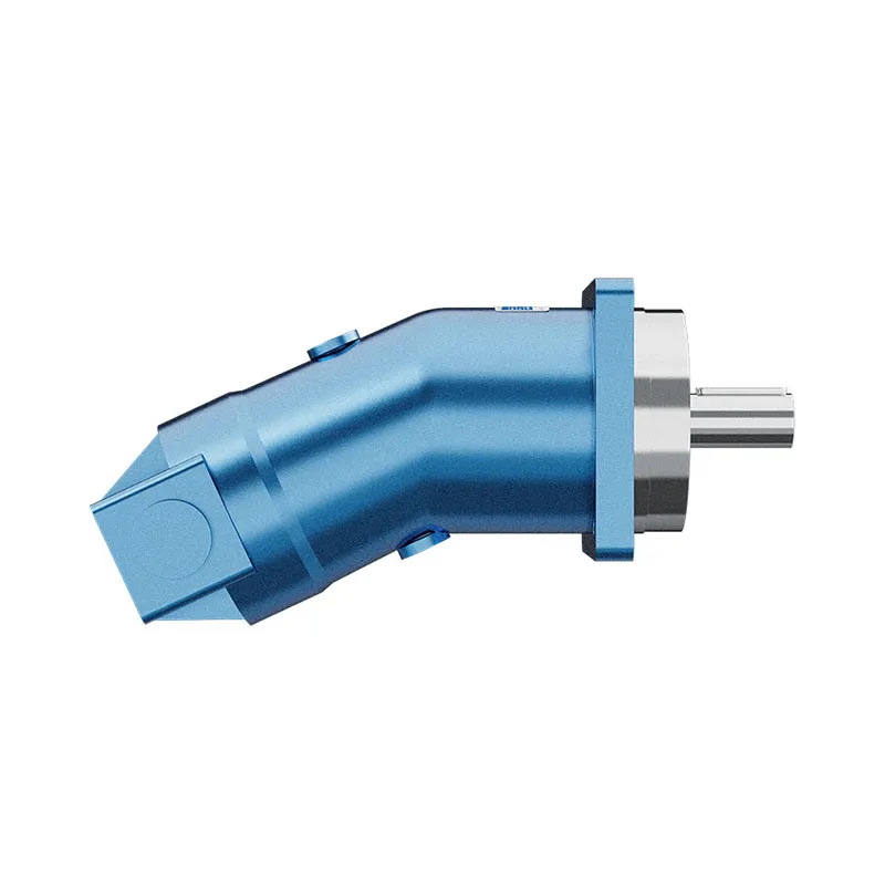
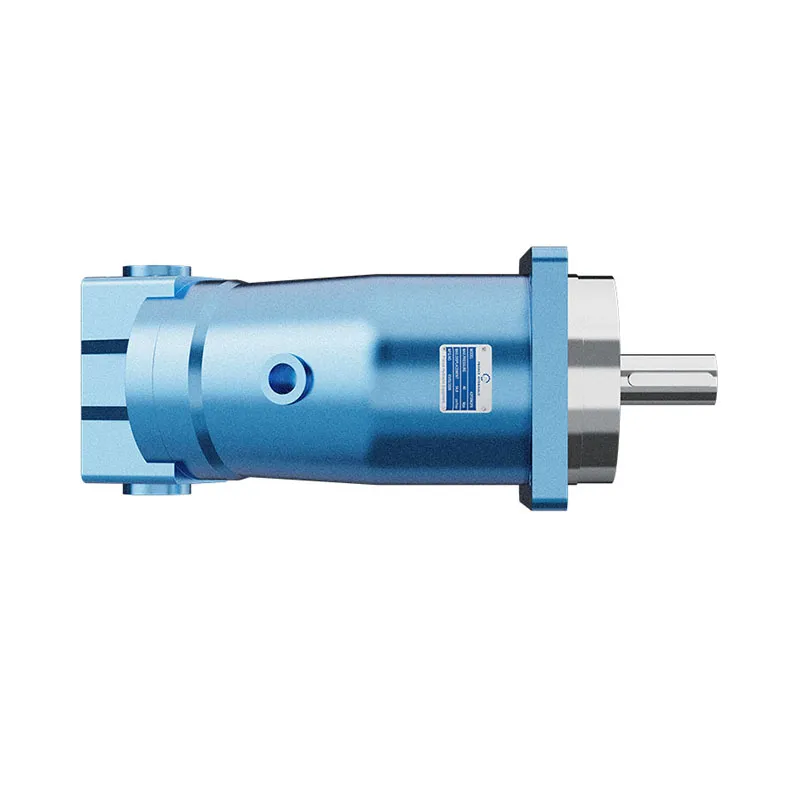
For a component enquiry, review Fixed Displacement Motor A2F and provide the full specification and installation conditions. Related guides: piston motor range, orbital motor range, motor case-pressure checks, motor drain-flow measurement, motor efficiency calculation, Hydraulic Motor Rotation Direction: Port Connections and Reversing, Hydraulic Motor Freewheeling Circuit: Bypass and Make-Up Flow. Product photographs illustrate catalog configurations; they do not establish a pressure, speed or shaft-load rating for an unconfirmed order.
University lecture: hydraulic motor fundamentals
NPTEL-NOC IITM presents a hydraulic-motor lesson from IIT Madras. The lecture supports the distinction between hydraulic input and shaft output used in this guide. Component-specific installation and operating limits still require the selected motor documentation.
Open the NPTEL hydraulic motors lecture.
Technical and safety references
- NPTEL: Fundamentals of Industrial Oil Hydraulics and Pneumatics
- NIOSH: preventing injuries from hazardous energy
- Technical reference: orbital-motor operating principles and installation
These references provide educational and technical context. A reference manufacturer model-specific ratings are not specifications for a Prance product and do not imply brand affiliation or authorization.