Wenzhou Prance Hydraulic Equipment Co., Ltd


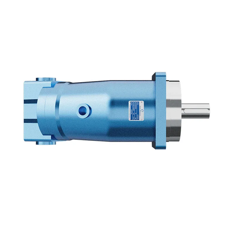
A2F Fixed Displacement Hydraulic Motor
The A2F product is listed as a fixed displacement hydraulic motor. Its family documentation also includes pump operating conditions, making the intended operating mode and rotation an essential part of selection rather than an assumption from the A2F name.
- Fixed displacement hydraulic motor listing
- ISO mounting flange reference
- Radial shaft-load review required
- Technical material includes separate pump and motor conditions
PRANCE HYDRAULIC · PRODUCT SERIES
A2F Fixed Displacement Hydraulic Motor
Axial piston; fixed displacement · Confirm motor operating mode and circuit
The A2F product is listed as a fixed displacement hydraulic motor. Its family documentation also includes pump operating conditions, making the intended operating mode and rotation an essential part of selection rather than an assumption from the A2F name.
Model
✓
Request a QuotationView Technical Data & DatasheetA2FAxial piston; fixed displacement
Confirm the complete model and approved specification with Prance Hydraulic. Product-series references alone do not establish interchangeability.
Configuration review · Technical documentation · Product selection
Product Details
- Fixed displacement hydraulic motor listing
- ISO mounting flange reference
- Radial shaft-load review required
- Technical material includes separate pump and motor conditions
CATEGORIES: Fixed Displacement Motor, Piston Motor
A2F Features & Application
Fixed displacement hydraulic motor listing
For a fixed displacement, flow and speed remain linked by the selected displacement. Check the actual operating point and efficiency.
ISO mounting flange reference
Check pilot diameter, bolt pattern, shaft engagement or port pattern against the approved installation drawing.
Radial shaft-load review required
Calculate the external radial and axial loads at their actual distance from the mounting face. Bearing type alone is not a load rating.
Technical material includes separate pump and motor conditions
Specify the full A2F order code, installation drawing and operating duty so the quotation can identify the proposed configuration.
A2F Specifications
| Series / model | A2F |
|---|---|
| Product type | A2F Fixed Displacement Hydraulic Motor |
| Design | Axial piston; fixed displacement |
| Circuit / selection | Confirm motor operating mode and circuit |
| Product role on this page | Hydraulic motor |
| Operating-mode check | Separate motor data from pump data in the family documentation |
A2F Selection & Configuration
The A2F product is listed as a fixed displacement hydraulic motor. Its family documentation also includes pump operating conditions, making the intended operating mode and rotation an essential part of selection rather than an assumption from the A2F name.
For a motor application, use the motor-specific pressure, speed and flow relationships. Do not apply a pump inlet-pressure condition to a motor port. Confirm fluid compatibility and the permissible radial load for the exact shaft and bearing arrangement.

Your Application.
The Right Configuration.
Hydraulic pumps · Hydraulic motors · Hydraulic valves
Send the A2F nameplate, operating requirements and installation drawing for a configuration review before quoting.
- Model review — send the full model code or an existing nameplate photograph.
- Interface matching — confirm shaft, mounting flange, rotation and ports.
- Operating conditions — provide flow, pressure, speed, fluid and duty cycle.
- Documentation — request the relevant product data and drawings for your review.

A2F Buying Guide
Use this sequence to prepare the A2F configuration for review and quotation.
- Define starting and continuous torque, speed range and duty cycle.
- Specify available flow, work-port pressure difference and return pressure.
- Confirm the displacement setting and required behavior during starting and stopping.
- Check shaft, mounting pilot, flange, port orientation and external loads.
- Review case drainage, replenishment and any displacement control.
- Specify fluid conditions and any independent braking requirement.
- Approve the complete model, operating envelope, drawing and quantity.
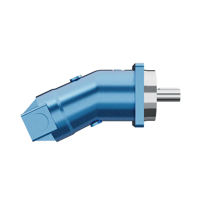
Selection, Documentation & Project Support

Selection Support
Learn more →Share your hydraulic circuit, operating point and installation requirements for a configuration discussion.
Flow · Pressure · Speed · Interfaces

Technical Resources
Learn more →Review product documentation, model codes and technical data before finalizing the specification.
Datasheets · Model codes · Drawings

Project Inquiries
Learn more →Send your required model, quantity, application and project requirements to discuss your inquiry.
Product inquiries · Configuration review
Configuration, Quantity & Delivery
Confirm the complete A2F code, approved drawing and operating limits. Availability, quantity, documentation and delivery date are confirmed in the quotation.
Discuss Your A2F Application
Send the full model code, operating duty, installation details and quantity.
Request a A2F QuotationA2F Questions Before Ordering
What type of product is the A2F?
A2F Fixed Displacement Hydraulic Motor. Design: Axial piston; fixed displacement. Confirm motor operating mode and circuit. Confirm the complete order code for the offered version.
Can a similar motor replace the A2F?
Only after checking the operating duty, interfaces and control requirements. A matching displacement, nominal size or photograph does not establish interchangeability. Compare the approved drawings and complete codes.
Which data is needed for a quotation?
Define starting and continuous torque, speed range and duty cycle. Specify available flow, work-port pressure difference and return pressure. Attach the nameplate, complete order code, installation drawing and required quantity.
A2F Technical Data & Documents
View A2F catalog data and operating conditions
Catalog reference for the model rows and variants explicitly identified below. Keep each value with its unit, duty condition and footnotes. Family tables may include related versions; confirm the complete offered code and approved data before ordering.
Technical Data
Inlet Operating Pressure: Pump : Minimum pressure at ports S, A or B: Pabs——————0. 08MPa In closed circuits, the feed pressure must be between 0.2MPa and 0.6MPa, depending on pump speed and viscosity of hydraulic fluid. •Motor: Pressure at port A or B: Nominal pressure——————–Pn =35MPa Peak pressure———————Pmax=40MPa The sum of the pressures at ports A and B must not exceed 7OMPa (individual pressure on either side max 40MPa) •outlet Operating Pressure •Pump: Nominal pressure————–Pn=35MPa Peak pressure————–Pmax=40MPa Maximum permissible case pressure(at port T): Pabs—————0.2MPa •Oil Temperature Range:-25℃~80℃ •Viscosity Range T min——————————————10mm2/s T max—————-( for short periods ) 1000mm2/s Optimum Operating Viscosity:—————————16-25mm2/s Fluid Recommendation :40 low-solidifing •Filtration of hydraulic Fluid: Recommended filtration 10um. Coarser filtration of 25 to40um is acceptable,However longer service life is achieved. •Speed Range: No limitation on minimum speed, If high uniformity of rotation is required,nmin should not be less than 50r/min,See table on page 5 for maximum speed. •Mounting position: Arbitrarily Choose, the housing must be filled with oil; •Flow direction:| Clockwise: | Anticlockwise: |
| A to B S toB(Open Circuit) | B to A S to A(Open Circuit) |
Rear cover:
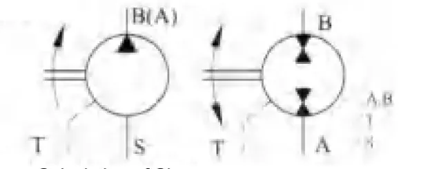 |
PresssurePort Drain Port Suction | ||
| Calculation of Size | |||
| pump: | Output Flow | Q=(Vg×n×ŋv)/1000 | [L/min] |
| Intput Torque | M=0.159×Vg×Δp/ŋmh | [N:m] | |
| Intput power | P=(Q×Δp)/(60×ŋt) | [Kw] | |
| Motor: | Input Flow | Q=(Vg×n)/(1000×ŋv) | [L/min] |
| Output Speed | n=(Q×1000×ŋv)/Vg | [r/min] | |
| Output Torque | M=0.159×Vg×Δp×ŋmh | [Nm] | |
| Output power | P=(Q×Δp×ŋt)/60 | [Kw] | |
| Vg=max geometric displacement | [ml/r] | ||
| M=torque | [N.m] | ||
| Δp=differential pressure | [Mpa] | ||
| n=speed | [r/min] | ||
| ηv=volumetric efficiency | |||
| ηm=mechanical- -hydraulic efficiency | |||
| ηt=overall efficiency | |||
| Used for close system pump. /motor | system | 10~160 | 200~500 | ||
| 1.A,B Thread |  |
6.A,B Flange | 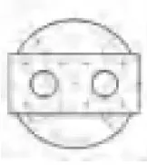 |
1. A,B Flange | |
| 2. A,B Flange |  |
7.A,B Flange |  |
 |
|
| Used for open system punp | 3.A,B Flange | 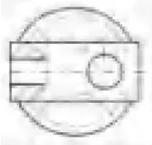 |
5.B,S Prick Worm | 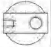 |
2.B,S Flange |
| 4.B,S Thread | 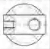 |
 |
|||
Technical Data Theoretical Values, Without Considering η m and ηV, Values rounded Off.
| Size | 10 | 12 | 23 | 28 | 45 | 55 | 63 | 80 | 107 | 125 | 160 | 200 | 250 | 355 | 500 | ||
| Displacement Vg(ml/r) | 9.4 | 11.6 | 22.7 | 28.1 | 44.3 | 54.8 | 63 | 80 | 107 | 125 | 160 | 200 | 250 | 355 | 500 | ||
| Max Speed n max(r/min) | Close Circuit | 7500 | 6000 | 5600 | 4750 | 4500 | 3750 | 4000 | 3350 | 3000 | 3150 | 2650 | 2500 | 2500 | 2240 | 2000 | |
| Open Circuit Inlet Pressure (Pabs=MPa) | 0.09 | 4700 | 3750 | 3750 | 2800 | 2850 | 2360 | 2550 | 2120 | 1900 | 2120 | 1650 | 1700 | 1400 | 1250 | 1120 | |
| 0.10 | 5000 | 4000 | 4000 | 3000 | 3000 | 2500 | 2700 | 2240 | 2000 | 2240 | 1750 | 1800 | 1500 | 1320 | 1200 | ||
| 0.15 | 6000 | 4900 | 4900 | 3600 | 3550 | 3000 | 3300 | 2750 | 2450 | 2750 | 2100 | 2180 | 1850 | 1650 | 1500 | ||
| Max Flow Q max(I/min) | Close Circuit | 71 | 70 | 127 | 133 | 199 | 206 | 253 | 268 | 321 | 394 | 424 | 500 | 625 | 795 | 1000 | |
| Open Circuit Inlet Pressure (Pabs=MPa) | 0.09 | 43 | 42 | 83 | 76 | 122 | 125 | 156 | 165 | 197 | 257 | 256 | 330 | 340 | 430 | 543 | |
| 0.10 | 46 | 45 | 88 | 82 | 129 | 133 | 165 | 174 | 208 | 272 | 272 | 349 | 364 | 455 | 582 | ||
| 0.15 | 55 | 55 | 108 | 98 | 157 | 159 | 202 | 213 | 251 | 333 | 326 | 423 | 449 | 568 | 728 | ||
| Max Power Pmax(Kw) Δp=35MPa | Close Circuit | 41 | 41 | 74 | 78 | 116 | 120 | 147 | 156 | 187 | 230 | 247 | 292 | 365 | 454 | 583 | |
| Open Circuit Inlet Pressure (Pabs =MPa) | 0.09 | 25 | 25 | 48 | 44 | 71 | 73 | 91 | 96 | 115 | 150 | 149 | 192 | 198 | 251 | 317 | |
| 0.10 | 27 | 26 | 51 | 48 | 75 | 78 | 96 | 101 | 121 | 159 | 159 | 204 | 212 | 265 | 340 | ||
| 0.15 | 32 | 32 | 63 | 57 | 92 | 93 | 118 | 124 | 148 | 194 | 190 | 247 | 262 | 331 | 424 | ||
| Electric Motor Speed n=1450/min | Flow Close Circuit | 13.6 | 16.8 | 32.9 | 40.7 | 64.2 | 79.5 | 91.3 | 116 | 155.2 | 181.2 | 232 | 290 | 363 | 515 | 725 | |
| Q(l/min)Open Circuit | 13.2 | 16.3 | 31.9 | 39.5 | 62.3 | 77.1 | 88.6 | 112.5 | 150.5 | 175.8 | 225 | 281 | 352 | 499 | 703 | ||
| P(Kw) Close Δp=35MPa Open | 7.9 | 9.8 | 19.2 | 23.7 | 27.4 | 46 | 53 | 67.7 | 90 | 106 | 135 | 169 | 212 | 300 | 423 | ||
| 7.7 | 9.5 | 18.6 | 23 | 36.3 | 45 | 51.7 | 66 | 88 | 1.3 | 131 | 169 | 212 | 300 | 423 | |||
| Torque(N.m) | Δp= 10MPa | 15 | 18 | 36 | 44.7 | 70 | 87 | 100 | 127 | 170 | 199 | 254 | 318 | 398 | 564 | 795 | |
| Δp=35MPa | 52 | 65 | 126 | 156 | 247 | 305 | 351 | 445 | 595 | 696 | 890 | 1113 | 1391 | 1976 | 2783 | ||
| Approx Weight (kg) | 5 | 5 | 12 | 12 | 23 | 23 | 33 | 33 | 44 | 63 | 63 | 88 | 88 | 138 | 185 | ||
Notes:
1.These values are valid provided there is an absolute pressure at suction inlet Sand when operated on mineral oil. Permissible speed nperm can be determined from the nomograph. In motor operation the permissible speed for closed circuit system and boosted operation are also valid for open circuit system. When suction pressure Pabs > 0. 1MPa, the permissible speed can be increased in open circuits (Self-suction operation). But when suction pressure Pabs < 0.1 MPa, the permissible speed must be reduced.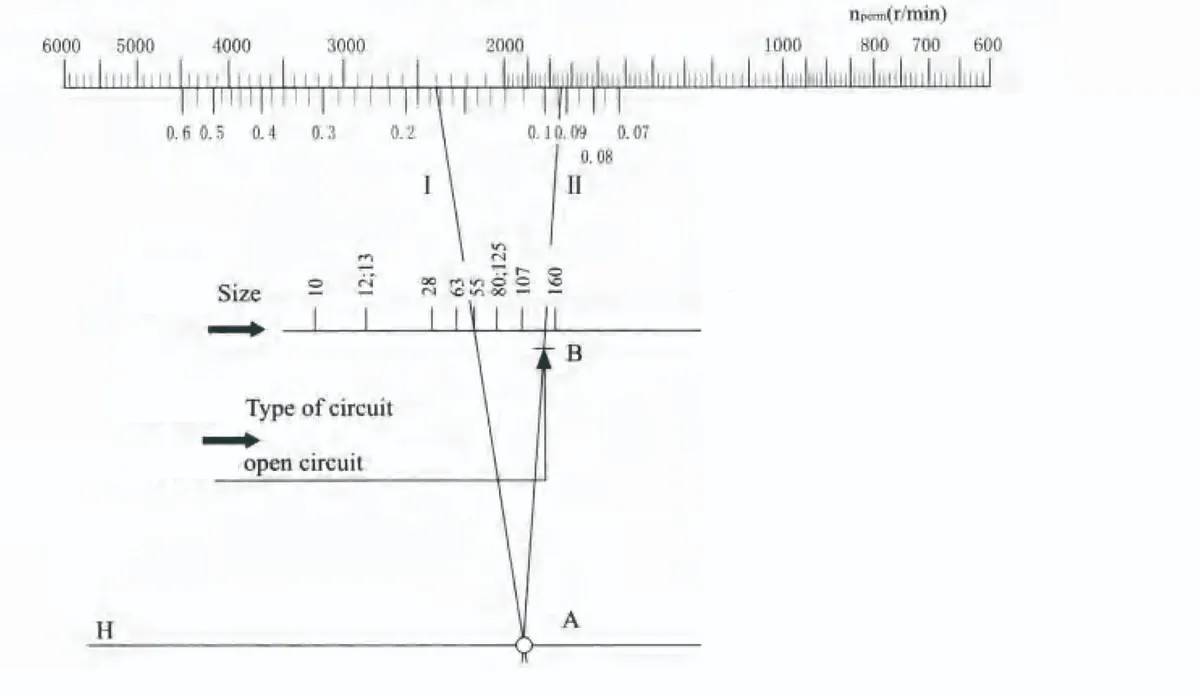 Example:
Given:size 55,Drive speed 2400r/min
Required:pressure Pabs at the suction Inlet S.
Solution:Line 1 on scale nperm drawn towards size 55 crosses line H at point A .line 11 from point A to point B(open circuit) gives the result:
Pabs > 0.094MPa.
The following are always used together:
1.Scales Pabs,type of circuit and line H.
2.Line H,size scale and nperm.
Related Selection Resources
Request a A2F Quotation
Tell us your required configuration, quantity and application.
Related Products
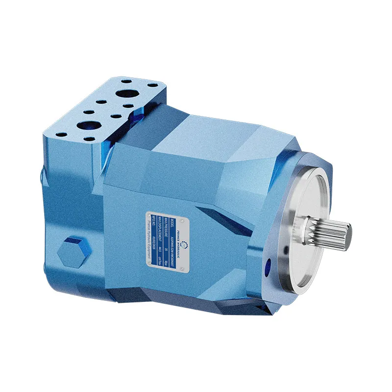
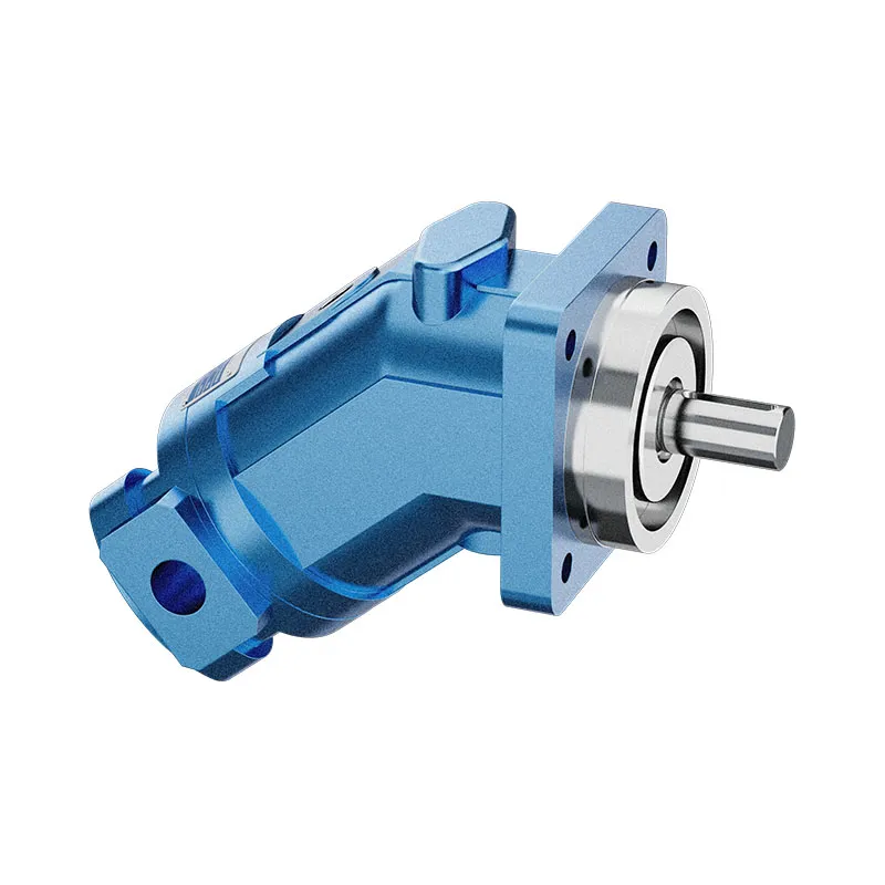
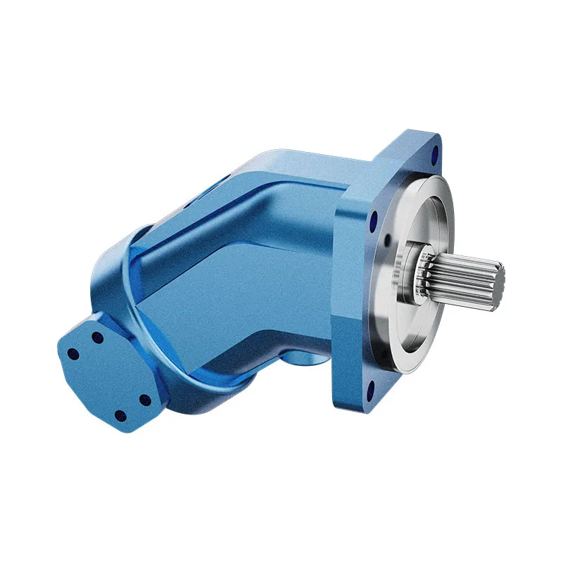
Compare related hydraulic motors and confirm the complete configuration for your application.

Technical Data
Inlet Operating Pressure:
Pump :
Minimum pressure at ports S, A or B: Pabs------------------0. 08MPa In closed circuits, the feed
pressure must be between 0.2MPa and 0.6MPa, depending on pump speed and viscosity of hydraulic fluid.
•Motor: Pressure at port A or B:
Nominal pressure--------------------Pn =35MPa
Peak pressure---------------------Pmax=40MPa
The sum of the pressures at ports A and B must not exceed 7OMPa
(individual pressure on either side max 40MPa)
•outlet Operating Pressure
•Pump: Nominal pressure--------------Pn=35MPa
Peak pressure--------------Pmax=40MPa
Maximum permissible case pressure(at port T):
Pabs---------------0.2MPa
•Oil Temperature Range:-25℃~80℃
•Viscosity Range
T min------------------------------------------10mm2/s
T max----------------( for short periods ) 1000mm2/s
Optimum Operating Viscosity:---------------------------16-25mm2/s
Fluid Recommendation :40 low-solidifing
•Filtration of hydraulic Fluid:
Recommended filtration 10um. Coarser filtration of 25 to40um is acceptable,However longer service life is achieved.
•Speed Range:
No limitation on minimum speed,
If high uniformity of rotation is required,nmin should not be less than 50r/min,See table on page 5 for maximum speed.
•Mounting position:
Arbitrarily Choose, the housing must be filled with oil;
•Flow direction:
| Clockwise: | Anticlockwise: |
| A to B S toB(Open Circuit) | B to A S to A(Open Circuit) |
Rear cover:
|
PresssurePort Drain Port Suction |
||
| Calculation of Size | |||
| pump: | Output Flow | Q=(Vg×n×ŋv)/1000 | [L/min] |
| Intput Torque | M=0.159×Vg×Δp/ŋmh | [N:m] | |
| Intput power | P=(Q×Δp)/(60×ŋt) | [Kw] | |
| Motor: | Input Flow | Q=(Vg×n)/(1000×ŋv) | [L/min] |
| Output Speed | n=(Q×1000×ŋv)/Vg | [r/min] | |
| Output Torque | M=0.159×Vg×Δp×ŋmh | [Nm] | |
| Output power | P=(Q×Δp×ŋt)/60 | [Kw] | |
| Vg=max geometric displacement | [ml/r] | ||
| M=torque | [N.m] | ||
| Δp=differential pressure | [Mpa] | ||
| n=speed | [r/min] | ||
| ηv=volumetric efficiency | |||
| ηm=mechanical- -hydraulic efficiency | |||
| ηt=overall efficiency | |||
| Used for close system pump. /motor |
system | 10~160 | 200~500 | ||
| 1.A,B Thread |
|
6.A,B Flange |
|
1. A,B Flange | |
| 2. A,B Flange |
|
7.A,B Flange |
|
|
|
| Used for open system punp |
3.A,B Flange |
|
5.B,S Prick Worm |
|
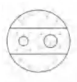
2.B,S Flange |
| 4.B,S Thread |
|
|
|||
Technical Data Theoretical Values, Without Considering η m and ηV, Values rounded Off.
| Size | 10 | 12 | 23 | 28 | 45 | 55 | 63 | 80 | 107 | 125 | 160 | 200 | 250 | 355 | 500 | ||
| Displacement Vg(ml/r) | 9.4 | 11.6 | 22.7 | 28.1 | 44.3 | 54.8 | 63 | 80 | 107 | 125 | 160 | 200 | 250 | 355 | 500 | ||
| Max Speed n max(r/min) |
Close Circuit | 7500 | 6000 | 5600 | 4750 | 4500 | 3750 | 4000 | 3350 | 3000 | 3150 | 2650 | 2500 | 2500 | 2240 | 2000 | |
| Open Circuit Inlet Pressure (Pabs=MPa) |
0.09 | 4700 | 3750 | 3750 | 2800 | 2850 | 2360 | 2550 | 2120 | 1900 | 2120 | 1650 | 1700 | 1400 | 1250 | 1120 | |
| 0.10 | 5000 | 4000 | 4000 | 3000 | 3000 | 2500 | 2700 | 2240 | 2000 | 2240 | 1750 | 1800 | 1500 | 1320 | 1200 | ||
| 0.15 | 6000 | 4900 | 4900 | 3600 | 3550 | 3000 | 3300 | 2750 | 2450 | 2750 | 2100 | 2180 | 1850 | 1650 | 1500 | ||
| Max Flow Q max(I/min) |
Close Circuit | 71 | 70 | 127 | 133 | 199 | 206 | 253 | 268 | 321 | 394 | 424 | 500 | 625 | 795 | 1000 | |
| Open Circuit Inlet Pressure (Pabs=MPa) |
0.09 | 43 | 42 | 83 | 76 | 122 | 125 | 156 | 165 | 197 | 257 | 256 | 330 | 340 | 430 | 543 | |
| 0.10 | 46 | 45 | 88 | 82 | 129 | 133 | 165 | 174 | 208 | 272 | 272 | 349 | 364 | 455 | 582 | ||
| 0.15 | 55 | 55 | 108 | 98 | 157 | 159 | 202 | 213 | 251 | 333 | 326 | 423 | 449 | 568 | 728 | ||
| Max Power Pmax(Kw) Δp=35MPa |
Close Circuit | 41 | 41 | 74 | 78 | 116 | 120 | 147 | 156 | 187 | 230 | 247 | 292 | 365 | 454 | 583 | |
| Open Circuit Inlet Pressure (Pabs =MPa) |
0.09 | 25 | 25 | 48 | 44 | 71 | 73 | 91 | 96 | 115 | 150 | 149 | 192 | 198 | 251 | 317 | |
| 0.10 | 27 | 26 | 51 | 48 | 75 | 78 | 96 | 101 | 121 | 159 | 159 | 204 | 212 | 265 | 340 | ||
| 0.15 | 32 | 32 | 63 | 57 | 92 | 93 | 118 | 124 | 148 | 194 | 190 | 247 | 262 | 331 | 424 | ||
| Electric Motor Speed n=1450/min |
Flow Close Circuit |
13.6 | 16.8 | 32.9 | 40.7 | 64.2 | 79.5 | 91.3 | 116 | 155.2 | 181.2 | 232 | 290 | 363 | 515 | 725 | |
| Q(l/min)Open Circuit |
13.2 | 16.3 | 31.9 | 39.5 | 62.3 | 77.1 | 88.6 | 112.5 | 150.5 | 175.8 | 225 | 281 | 352 | 499 | 703 | ||
| P(Kw) Close Δp=35MPa Open |
7.9 | 9.8 | 19.2 | 23.7 | 27.4 | 46 | 53 | 67.7 | 90 | 106 | 135 | 169 | 212 | 300 | 423 | ||
| 7.7 | 9.5 | 18.6 | 23 | 36.3 | 45 | 51.7 | 66 | 88 | 1.3 | 131 | 169 | 212 | 300 | 423 | |||
| Torque(N.m) | Δp= 10MPa | 15 | 18 | 36 | 44.7 | 70 | 87 | 100 | 127 | 170 | 199 | 254 | 318 | 398 | 564 | 795 | |
| Δp=35MPa | 52 | 65 | 126 | 156 | 247 | 305 | 351 | 445 | 595 | 696 | 890 | 1113 | 1391 | 1976 | 2783 | ||
| Approx Weight (kg) | 5 | 5 | 12 | 12 | 23 | 23 | 33 | 33 | 44 | 63 | 63 | 88 | 88 | 138 | 185 | ||
Notes:
1.These values are valid provided there is an absolute pressure at suction inlet Sand when operated on mineral oil.
Permissible speed nperm can be determined from the nomograph. In motor operation the permissible speed for closed circuit system and boosted operation are also valid for open circuit system. When suction pressure Pabs > 0. 1MPa, the permissible speed can be increased in open circuits (Self-suction operation). But when suction pressure Pabs < 0.1 MPa, the permissible speed must be reduced.
Example:
Given:size 55,Drive speed 2400r/min
Required:pressure Pabs at the suction Inlet S.
Solution:Line 1 on scale nperm drawn towards size 55 crosses line H at point A .line 11 from point A to point B(open circuit) gives the result:
Pabs > 0.094MPa.
The following are always used together:
1.Scales Pabs,type of circuit and line H.
2.Line H,size scale and nperm.