Wenzhou Prance Hydraulic Equipment Co., Ltd

Can a Hydraulic Gear Pump Run in Reverse? Rotation and Port Checks
A hydraulic gear pump can run in reverse only when its exact design and configuration permit that rotation. A clockwise-only pump is not made reversible by swapping the inlet and outlet hoses. Pressure balancing, shaft-seal drainage, lubrication paths and port sizing may depend on the intended direction. Some pumps are purpose-built for bidirectional service; some can be converted using an approved procedure. Others cannot. Before reversing a drive, establish the full pump code, shaft-view convention, circuit arrangement and manufacturer instructions. This guide explains the difference and provides a practical replacement and troubleshooting checklist.
Separate three different questions
Changing shaft rotation, changing the position of the ports and reversing actuator movement are different operations. A pump can turn in one direction while a directional valve reverses a cylinder or motor. An actuator running backwards therefore does not prove that the pump is turning backwards. Follow the circuit before touching the drive or connections.
On an external gear pump, liquid travels around the outside of the meshing gears from inlet to outlet. It does not move through the central meshing region. Reversing rotation changes the natural direction in which the tooth spaces transport liquid. That simple geometric observation does not mean every passage, bearing and seal is suitable for the new high-pressure side.
A manufacturer may offer clockwise and counterclockwise versions with a similar exterior. A reversible option may have additional internal arrangements. Treat the exact ordered code as the controlling evidence. A casting number or photograph can identify a family but generally cannot establish which internal pressure-balancing configuration is installed.
Why one-way construction can be damaged
Pressure acts on the gears and bearing blocks. In a compensated construction, pressure-fed areas help control axial clearance and leakage. Seals or passages direct high-pressure oil to the intended areas. Reversing the pressure relationship can put those parts in an unintended condition, increase leakage or prevent correct clearance control. The exact mechanism depends on the design.
The shaft seal is another concern. Its cavity may drain internally to the intended low-pressure port. If reverse operation makes that passage high pressure, the seal may experience a pressure for which it was not designed. An external leak after a drive change should prompt a complete review of rotation and drainage, rather than an immediate assumption that the seal material was defective.
Port dimensions may also be asymmetric. A larger inlet limits suction losses; a smaller discharge port may be acceptable under positive pressure. Swapping those functions can create excessive inlet restriction. A pump that delivers some flow at no load may still suffer incomplete filling or lubrication problems as speed and load increase. A brief successful trial is not evidence of approved reverse operation.
Read the shaft-view convention
Clockwise and counterclockwise descriptions must state the viewing direction. Hydraulic pump rotation is often identified when looking at the exposed drive-shaft end, but the exact manufacturer's convention must be confirmed. Looking from the opposite end reverses the apparent direction. Mark the observer location on the installation drawing to eliminate ambiguity between purchasing, maintenance and the drive supplier.
A coupling, gearbox or belt arrangement can change what the mechanic sees. Verify the output that actually drives the pump, not the direction observed at an unrelated motor fan. An electric motor's phase sequence can affect rotation, but changing electrical connections is work for a qualified person using the applicable isolation and electrical procedures.
Do not use an energized shaft as a convenient visual test point. Protective guards and safe inspection methods matter. If the manufacturer permits a brief unloaded rotation check, use the specified method and establish that the pump is filled, lubricated and protected. There is no universal safe dry-running interval for a gear pump.
Identify whether conversion is permitted
A legitimate conversion procedure comes from the manufacturer for the exact model. It may describe repositioning bearing blocks, seals, covers or port connections. It may require new sealing parts, a particular assembly orientation and an acceptance test. A procedure for a visually similar pump is not enough: internal compensating details can differ while the housing appears unchanged.
| Pump description | What must be confirmed | Suitable decision |
|---|---|---|
| Clockwise-only ordered code | Rotation convention and inlet location | Keep the specified drive direction |
| Counterclockwise-only ordered code | Matching opposite-rotation construction | Match the replacement to the actual drive |
| Manufacturer-convertible model | Exact conversion instructions and required parts | Use the approved workshop procedure |
| Bidirectional pump | Ratings and drain arrangement in both directions | Design the circuit around its documented capability |
| Unknown pump with swapped hoses | Internal configuration and pressure relationships | Stop and identify it before operation |
Supporting technical context: NPTEL: industrial oil hydraulics, NPTEL: gear pump construction. Illustrative calculations and qualitative checks do not establish a product rating or universal acceptance limit.
This is a qualitative decision table. It does not assign ratings to an unidentified component. Gear pump geometry explains fluid transport; the manufacturer's configuration documentation establishes permitted service.
A conversion should leave a traceable record showing the original configuration, work performed, parts replaced, final rotation and test results. Relabel the component only using the approved identification process. Leaving an old rotation marking after a conversion can cause the next replacement to be ordered incorrectly.
Why switching hoses can make the situation worse
The inlet side normally draws from a reservoir or another approved supply. The pressure side feeds a circuit with protection appropriate to the pump. Exchanging hoses can connect the reservoir to a port not intended for suction, disconnect the effective relief path or send pressure into components intended for return service. Review the entire circuit rather than evaluating the pump in isolation.
A return line, reservoir fitting or filter housing may have a much lower permitted pressure than a pressure line. Never assume that every hose attached to the same pump can safely experience discharge pressure. Check component ratings and flow direction, including any filter, check valve, cooler and pressure protection in the route.
In a reversible system, the design must maintain inlet supply and pressure protection for both flow directions. The pump manufacturer and system designer should establish how make-up flow, trapped volume and seal drainage are handled. A two-port appearance does not prove that the pump can perform the function of a hydraulic motor or a closed-loop transmission pump.
Diagnose reverse operation without repeating it
If the problem began after replacing an electric motor, changing a gearbox or reconnecting a drive, compare the before-and-after configuration records first. Collect the pump model, drive model, rotation markings, circuit drawing and photographs taken with the equipment safely isolated. Record what changed and when the first symptom appeared.
Useful symptoms include no delivery, a sudden suction noise, abnormal current draw, overheating or a new shaft-seal leak. None is unique to reverse rotation. Low reservoir level, blocked suction, an open bypass or a damaged coupling can create overlapping symptoms. The purpose of the evidence review is to test several explanations while avoiding further damage.
A qualified team can establish actual drive rotation using an approved protected method. Compare the result with the pump documentation. If it is wrong, correct the drive arrangement before another operating test. A pump that has been run in the wrong direction may require inspection or a controlled workshop test; restoring the direction alone does not prove that no damage occurred.
Order a replacement that matches the drive
A replacement enquiry should state rotation explicitly with the observer position. Provide the full existing code, displacement, mounting flange, shaft details and port arrangement. Include speed, pressure, fluid and temperature requirements. If the drive must reverse during normal duty, describe that requirement as bidirectional service rather than requesting a generic replacement gear pump.
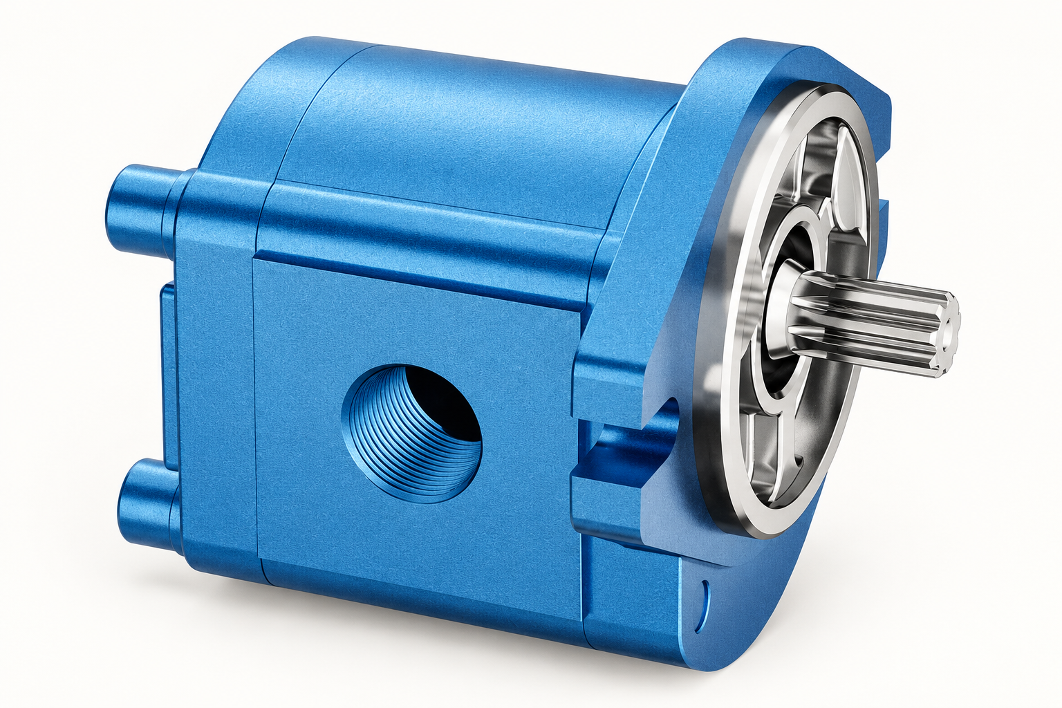
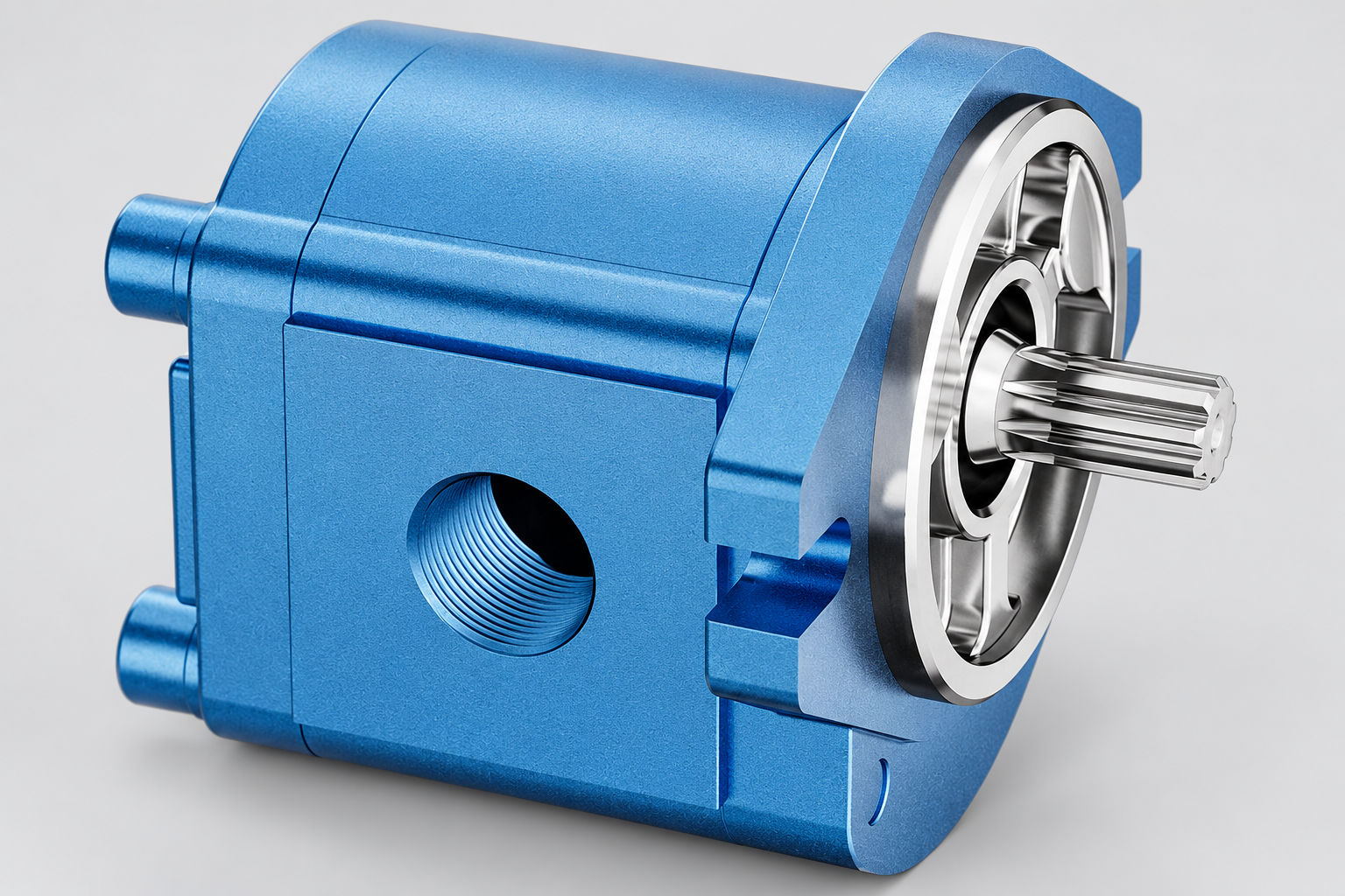
Prance lists an HDH external gear pump and an HG internal gear pump family. These are different pumping architectures and should not be treated as interchangeable because both contain gears. Catalogue photographs show external identification features. They do not establish reverse-running capability or a conversion procedure for a particular order.
Ask the supplier to confirm the exact code offered, the documented rotation, permitted inlet conditions and the seal-drain arrangement. Request a drawing that labels inlet and outlet for the ordered direction. For a conversion or bidirectional application, obtain written configuration confirmation and agree the test scope before purchase.
Acceptance checks after a correction
After the cause has been resolved, verify fluid condition, inlet supply, coupling alignment and the circuit protection. The pump must be prepared according to its instructions. Inspect for contamination or debris if there is reason to suspect internal damage. Replacing a failed unit without removing debris can transfer the original problem to the new pump.
During an approved test, record speed, outlet pressure, inlet condition, flow and temperature. Observe external leaks and drive load. Compare delivery with the manufacturer's stated test conditions rather than with an uncorrected theoretical flow value. A check at only one low-load operating point may miss problems that occur under pressure.
Keep the final rotation photograph or diagram, ordered code and commissioning record together. Clear identification is especially useful on machines with several pumps or a tandem drive. A future technician should be able to establish which shaft direction belongs to each pump without guessing from hose routing.
Frequently asked questions
Can I reverse a clockwise gear pump by swapping its hoses?
Not unless the exact design and circuit are approved for that operation. Internal drainage, pressure balancing and inlet sizing may depend on direction. Swapping hoses can also compromise protection elsewhere in the system.
Are all external gear pumps reversible?
No. Some are built for one rotation, some are convertible under a manufacturer procedure and some are purpose-built for bidirectional duty. The ordered code and documentation distinguish these cases.
Is counterclockwise viewed from the motor or pump shaft?
Confirm the manufacturer's convention. Describe the observer position explicitly, preferably with a drawing. Looking at the opposite end reverses the apparent direction and can cause an otherwise correct replacement to be ordered incorrectly.
Does a pump survive a short wrong-direction test?
There is no universal guaranteed safe interval. Lubrication, inlet supply, speed and internal design affect the consequences. Stop the unintended operation and use the manufacturer's inspection or test advice before returning the unit to service.
Can a gear pump be used as a hydraulic motor?
Only if it is designed and rated for that service. Pump appearance and basic reversibility do not establish shaft-load capacity, starting behaviour, drainage requirements or motor operating limits. Request a documented motor configuration for a motor application.
Related products and engineering guides
External Gear Pump HDH, related hydraulic product range, What record should verify a pump's rotation direction?, Hydraulic Gear Pump Wear: Read the Pattern Before Replacing the Pump, Hydraulic Pump Replacement Checklist: 15 Specifications to Match. Provide the circuit, fluid, duty and exact ordered configuration when requesting component-specific data.
University lesson: mod-40 lec-42 AppendicesTutorial on Basic Calculation on HST System and Hydraulic Fluids
This NPTEL university lecture explains the component principles underlying this guide; the lecture is background education rather than a configuration-specific test procedure.

Technical references
Sources support the stated principles and method scope. Illustrative inputs and another manufacturer’s documents do not establish Prance component ratings, warranties or brand affiliation.