Wenzhou Prance Hydraulic Equipment Co., Ltd

Hydraulic Valve Subplate Leakage: Mounting Face and Seal Diagnosis
Hydraulic valve subplate leakage is an external leak at the interface between a mounted valve and its supporting plate or manifold. Common causes include a damaged or misplaced seal, contamination on the mounting face, incompatible port geometry, uneven clamping or a damaged surface. The correct response is to isolate the system, identify the actual leak origin and compare the installed parts with their drawings. Tightening bolts blindly can distort the assembly without solving the cause. This guide explains how to separate mounting-interface leakage from other faults and what evidence to request before repair or replacement.
First prove where the oil originates
Oil found below a valve can travel from a connector, pilot connection, neighbouring fitting or another component. Gravity, airflow and the shape of the assembly can carry fluid across the mounting joint. Photograph the condition and record which areas first become wet during an approved observation procedure. Do not identify the failure solely from the final puddle location.
Separate external leakage from internal leakage. Oil passing between internal valve galleries or across the spool can affect actuator behaviour without escaping outside. A leak at the mounting interface can also connect adjacent passages internally if the sealing arrangement fails. These are different observations requiring different tests. A visible joint leak does not prove spool wear, and actuator drift does not automatically prove a failed mounting seal.
High-pressure hydraulic fluid can penetrate skin. Never use a finger or hand to find a leak, and do not loosen a fastener while the system is pressurised. Follow the equipment's hazardous-energy isolation procedure, including trapped pressure and stored mechanical energy. A stopped pump alone does not establish that the valve assembly is safe to open.
Match the mounting pattern and seal layout
A nominal valve size or family name is not a complete interface specification. Compare the valve drawing with the subplate drawing, including port positions, mounting holes, sealing areas and any pilot or drain passages. A close physical fit can conceal a mismatch that leaves a seal unsupported or connects the wrong galleries.
Directional-valve mounting patterns are commonly described using an applicable standard and size designation. Confirm the exact standard, revision and configuration claimed by the supplier. Do not infer interchangeability from a bolt pattern alone. The sealing arrangement and any additional passages remain part of the comparison.
For an existing machine, obtain the original assembly drawing and the full valve code. Record any sandwich valve, spacer or intermediate plate in the stack. Each added interface has its own seals and mounting requirements. A leak that appears to be under the main valve may actually originate at an intermediate interface hidden from the first viewing angle.
Inspect seals without guessing their specification
A flattened, cut, extruded, twisted or hardened seal suggests different mechanisms, but appearance alone does not establish the original material or size. Compare the removed seal with the approved parts list. Record the seal location and orientation before removal. Mixing several seals from a dismantled stack can make the failure analysis unreliable.
Check whether the seal was correctly retained during installation. A seal that falls from its recess or rolls during assembly can be pinched even when the final bolt torque is correct. Debris, excess adhesive or an unapproved lubricant can interfere with seating. Use the manufacturer's assembly instructions and compatible materials.
Fluid and temperature compatibility matter. A seal selected only by diameter may have an unsuitable material, hardness or cross-section. Do not replace the specified seal with the nearest available O-ring and then treat a successful low-pressure trial as proof of compatibility. Procurement should preserve the exact approved seal specification or a formally reviewed replacement.
Evaluate the mounting face
Inspect the cleaned faces under suitable lighting after isolation and disassembly. Look for raised burrs, scratches across sealing lands, embedded particles, corrosion, impact damage and witness marks from uneven loading. A small raised defect can prevent uniform contact and concentrate load around a seal. A scratch connecting a pressure passage to the edge is particularly relevant to an external leak.
Flatness and surface finish must be checked against the applicable drawing or manufacturer instructions. There is no universal acceptable roughness or flatness value for every hydraulic valve interface. A ruler placed across the face is not necessarily sufficient to verify a specified geometric tolerance. Use an appropriate measurement method and record its resolution.
Do not grind, lap or file a mounting face casually. Removing material can alter sealing recess depth, port support or the stack geometry. A workshop repair requires a verified method and an acceptance check. If the drawing and permissible repair limits are unavailable, escalate the part for engineering review rather than machining it until the leak disappears.
Check clamping and fasteners
The fasteners must have the correct diameter, grade, length and engagement for the assembly. A bolt can reach an apparent tightening value because it bottoms in a blind hole, while providing insufficient clamping. An incorrect washer, spacer or stack height can create a similar problem. Compare actual hardware with the assembly drawing.
The specified torque depends on the fastener and installation conditions. Thread lubrication, coatings and friction affect the relationship between applied torque and clamp load. Use the manufacturer's stated conditions and tightening sequence. Do not substitute a torque from another valve size or increase it beyond the approved value to force the joint closed.
Uneven clamping can distort a valve body or intermediate plate. This can cause leakage and potentially affect spool movement. After a leak repair, the team should verify both sealing and normal valve operation. Correcting the external leak while introducing a sticking spool is not an acceptable result.
A cause-to-evidence decision table
| Observation after safe inspection | Possible explanation | Evidence to collect | Correct next step |
|---|---|---|---|
| Cut or pinched seal | Assembly displacement or sharp edge | Seal position, recess and edge condition | Use approved replacement and correct assembly |
| Extruded sealing material | Unsupported gap or unsuitable configuration | Port support, seal specification and pressure history | Review the interface and seal requirements |
| Leak began after replacement | Pattern, stack or hardware mismatch | Original and new drawings and full codes | Resolve compatibility before testing |
| Wet joint with intact seals | Surface defect or clamping issue | Face measurements and fastener engagement | Repair or replace under an approved method |
| Oil trails from above | Another connection is the origin | First-wetting location and component map | Investigate the actual source |
Supporting technical context: NPTEL: directional valves and hydraulic sealing, NPTEL: directional valve configurations. Illustrative calculations and qualitative checks do not establish a product rating or universal acceptance limit.
The table gives qualitative hypotheses, not diagnostic certainty. Confirm the cause with the exact configuration and measured evidence. It does not provide a universal seal size, bolt torque or mounting-face tolerance.
Separate tank pressure from supply pressure
A valve's tank or drain passage may have different pressure limits from its supply passage. Return restriction or an incorrect drain connection can expose an interface seal or valve feature to an unintended condition. A team concentrating only on pump pressure may miss this contribution to repeated leakage.
Record pressures at relevant points during an approved test. Include the operating event that coincides with the leak: shifting, simultaneous actuator movement, cold start or reversal, for example. Do not assume a gauge at the pump represents the pressure at every passage in the valve stack.
If the leak returns after several seal replacements, stop treating the seal as the sole cause. Review circuit routing, return restrictions, pressure transients, assembly compatibility and mounting support. A repeated failure pattern is useful evidence; it should not become a routine instruction to install another identical seal without investigating the system.
Build a repair and purchasing record
The repair record should include valve and subplate identification, seal part numbers, fastener specification, mounting-face findings and the approved assembly procedure. Photograph the faces and seal locations before the parts are reassembled. Record any replaced intermediate plates or changes to the stack.
For a replacement enquiry, send both mating drawings and the circuit. State operating pressure, return pressure, fluid, temperature and the relevant duty. Explain whether the requested part is a main directional valve, a subplate or a complete assembly. A supplier cannot verify the interface from a single exterior photograph alone.
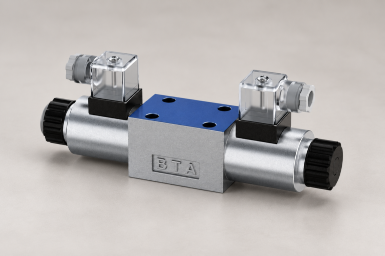
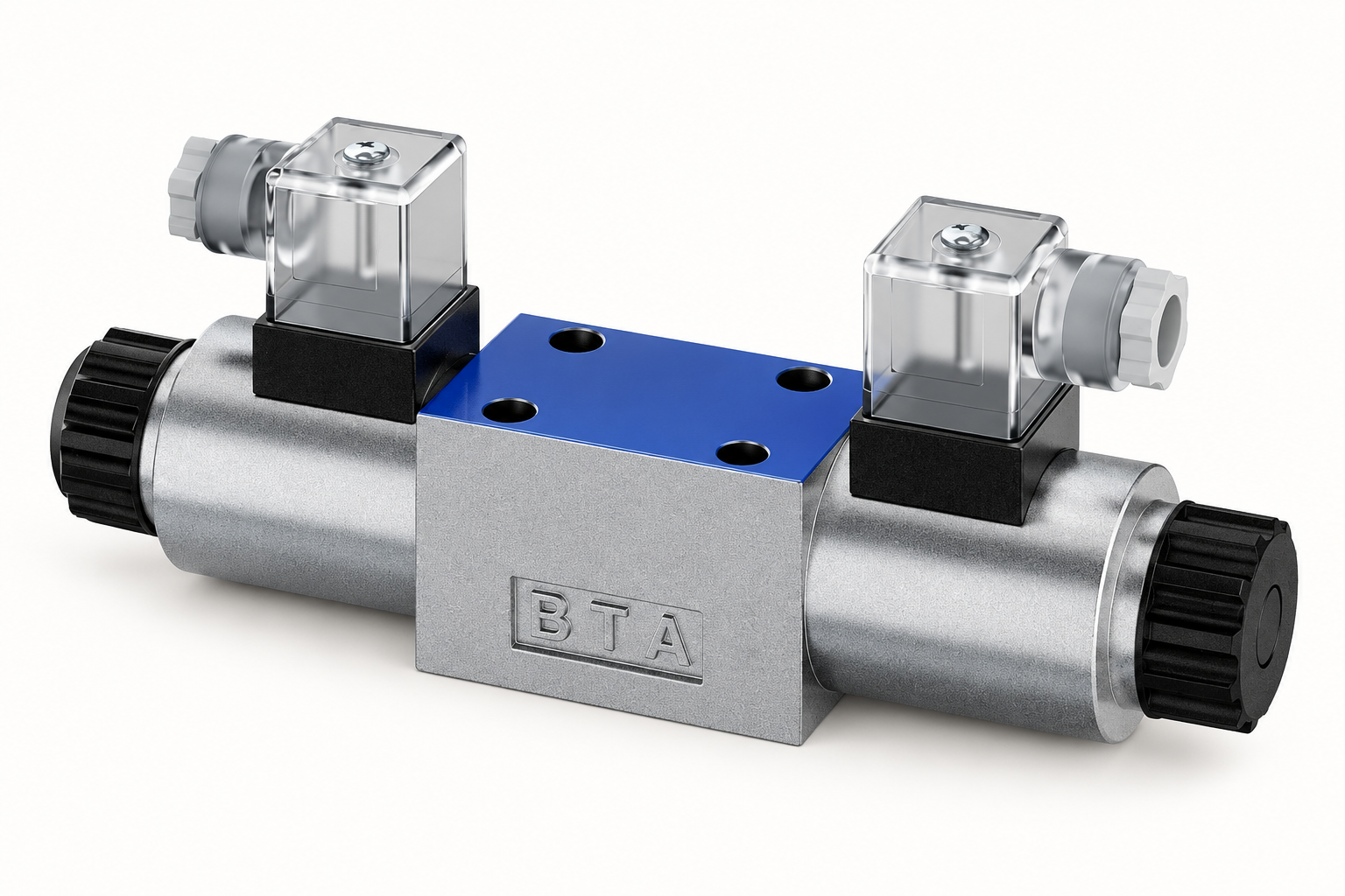
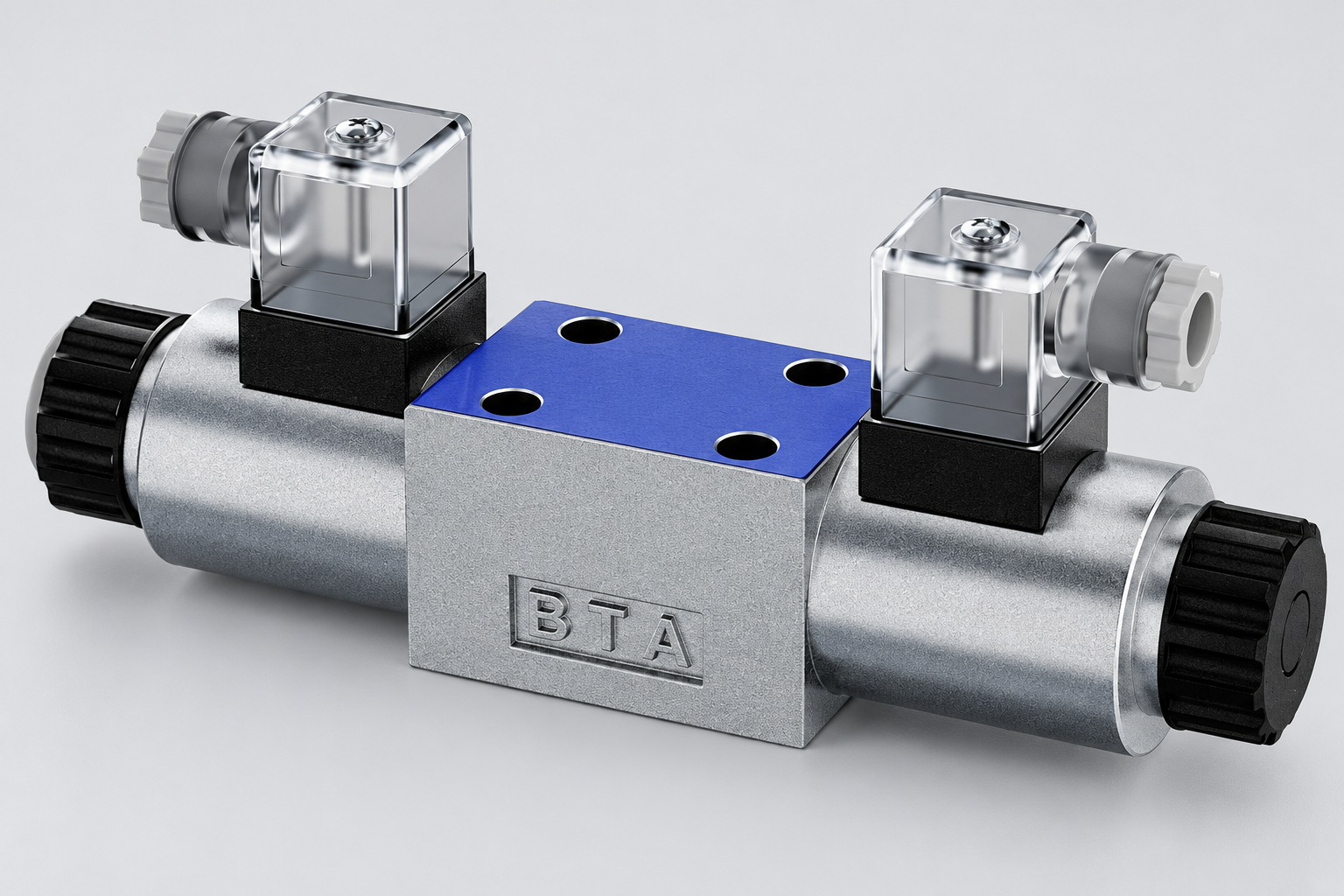
Prance's 4WE directional valve provides a relevant product reference for this topic. The illustrations show its catalogue exterior and solenoid arrangement. They do not show the concealed underside or establish mounting-face dimensions. Obtain the ordered mounting drawing and sealing instructions before assembly; do not use an illustration as a dimensional installation document.
Verify the repair before closing the job
With the assembly restored under the approved procedure, check connections, guarding and circuit protection. Conduct a controlled test using defined pressure and temperature conditions. Observe the interface safely and verify valve operation through the relevant positions. Include the event that originally produced the leak when it can be reproduced within approved limits.
Record the test conditions and duration rather than writing only that the leak was fixed. A joint that stays dry at idle may leak during hot operation or a pressure transient. If the acceptance plan requires checks at several conditions, complete them and record the result separately for each.
After the test, inspect for residual oil that could be mistaken for a new leak. Keep the evidence with the maintenance record so the next inspection can establish whether the condition has returned. If the cause remains uncertain, label that uncertainty plainly and arrange a focused follow-up rather than declaring a definitive root cause.
Frequently asked questions
Should I tighten the valve bolts until the leak stops?
No. Use the specified hardware, torque conditions and sequence. Excess tightening can distort parts, damage threads or affect spool movement. Establish the actual leak source and inspect the interface first.
Can an identical bolt pattern still have an incompatible interface?
Yes. Port locations, sealing support, pilot passages and stack details also matter. Compare both mating drawings and exact component codes rather than relying only on nominal valve size or mounting holes.
Does an external joint leak prove internal spool wear?
No. External mounting leakage and internal spool leakage are different faults. Oil can also travel from a nearby connection. Use evidence that distinguishes the observed leak path before selecting a repair.
What flatness tolerance should I use?
Use the value specified for the exact valve and mating surface. There is no universal tolerance for every interface. Verify the measurement method and resolution rather than using an assumed number from another product.
Why does a new mounting seal fail again?
Possible reasons include incompatible material, incorrect assembly, damaged faces, unsuitable clamping or an unintended pressure condition. Repeated replacement without reviewing these causes can leave the underlying problem unresolved.
Related products and engineering guides
Directional Valve 4WE, related hydraulic product range, Subplate Mounting Hydraulic Valve: Applications & Advantages, Hydraulic Directional Valve Internal Leakage Test, Hydraulic Valve Seal Materials: NBR, FKM, and EPDM Compatibility. Provide the circuit, fluid, duty and exact ordered configuration when requesting component-specific data.
University lesson: 5.1 – Directional Control Valves
This NPTEL university lecture explains the component principles underlying this guide; the lecture is background education rather than a configuration-specific test procedure.
Technical references
- NPTEL: directional valves and hydraulic sealing
- NPTEL: directional valve configurations
- NIOSH: hazardous-energy isolation
Sources support the stated principles and method scope. Illustrative inputs and another manufacturer’s documents do not establish Prance component ratings, warranties or brand affiliation.