Wenzhou Prance Hydraulic Equipment Co., Ltd

Hydraulic Brush-Cutter Motor Selection: Blade Inertia, Speed, and Coast-Down
Hydraulic brush cutter motor selection starts with the blade’s required working speed, the torque needed during cutting, and the energy that must be controlled during a stop. Match these demands to the carrier’s measured hydraulic supply under load and to the attachment manufacturer’s limits. A displacement chosen only from free-running flow can produce acceptable unloaded speed yet stall in vegetation, overload the shaft, or create an unsafe coast-down condition. Treat motor, cutter head, mounting, valves, and carrier as one engineered drive. The calculations below describe a preliminary review; they do not approve a particular motor for a cutting attachment.
Define the cutter duty before choosing displacement
Record the attachment’s permitted rotation direction, blade assembly, operating speed range, cutting conditions, and maximum allowable speed. These belong to the actual cutter design. Do not infer them from a similar-looking machine or from a motor catalog. Different blade diameter, blade mass, hub construction, and guarding can change the safe operating envelope even when hydraulic power appears similar.
Separate normal cutting from startup, repeated impacts, jam recovery, and stopping. Steady operation establishes a sustained power demand. Startup adds acceleration torque. An impact can impose a short pressure excursion and shaft load. A jam may stop rotation while the hydraulic system continues supplying energy. These events require different checks and should not be compressed into one average torque figure.
For procurement, describe the intended vegetation, duty duration, carrier, and operating environment in plain terms. Support these descriptions with attachment data and measurements. A statement such as “heavy duty” supplies no usable speed, torque, or bearing-load requirement and cannot replace an engineering duty profile.
Establish what the carrier supplies at the attachment
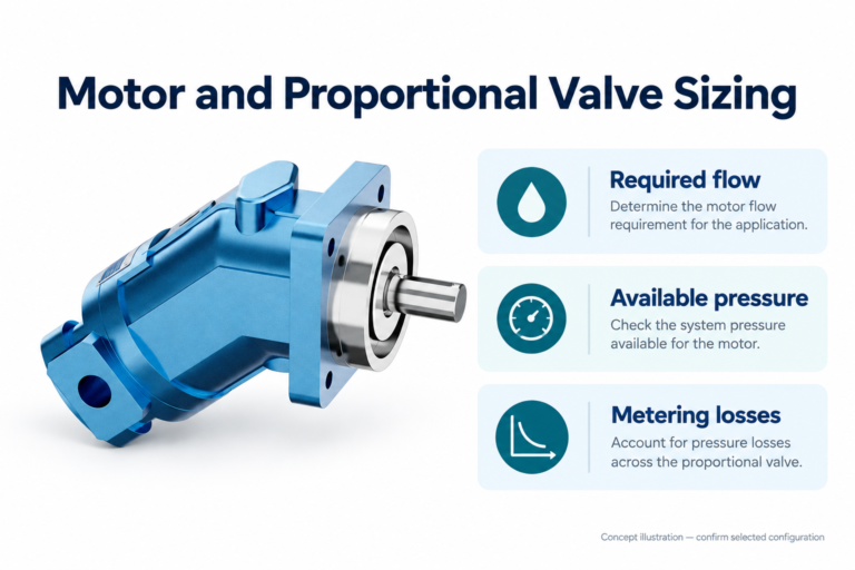
Obtain flow and pressure at the attachment connection under representative working conditions. Published auxiliary-flow capacity may describe a favorable engine speed or a particular control setting. Shared functions, pump control, hot-oil leakage, coupler restriction, and return pressure can change what reaches the motor during cutting. Specify the measurement location and whether another hydraulic function was active.
The motor pressure difference is the difference between its working ports. Pump outlet pressure alone does not establish shaft torque. Supply losses, return restriction, and control-valve losses consume part of the pressure budget. Record return pressure separately and compare it with the complete ordered motor’s permitted operating conditions. Case pressure is another limit and must not be assumed equal to working-port pressure.
Also identify oil type, temperature range, cleanliness requirements, filtration arrangement, and any dedicated case-drain requirement. Verify these against manufacturer documentation. An attachment whose continuous demand exceeds the carrier’s sustainable cooling or flow capacity cannot be made compatible simply by fitting a larger motor.
Use displacement calculations as a first screen
For a fixed-displacement motor, theoretical speed in revolutions per minute is approximately 1000 times inlet flow in liters per minute divided by displacement in cubic centimeters per revolution. Actual speed is lower when internal leakage is represented by volumetric efficiency. The useful screening relationship is n = 1000 Q ηv / Vd. Efficiency is an operating-point input, not a universal constant for all pressures and temperatures.
Consider a hypothetical requirement of 1000 rpm with 50 L/min reaching the motor. If an assumed volumetric efficiency of 0.90 is used only for preliminary arithmetic, displacement is 1000 × 50 × 0.90 / 1000 = 45 cm³/rev. This is not a recommendation for a cutter or a rating for the illustrated product. Repeat the calculation using the actual efficiency information and the lowest available working flow.
Increasing displacement generally lowers speed for the same available flow and increases theoretical torque for the same pressure difference. That tradeoff does not establish a safe blade speed, shaft capacity, or motor life. The resulting operating point still needs to fit the manufacturer’s speed, pressure, bearing, lubrication, and thermal limits.
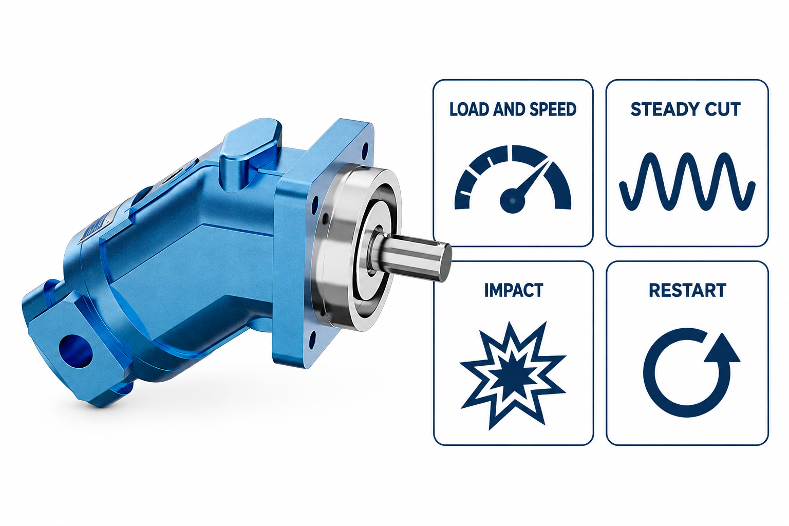
Check torque, power, and startup separately
Theoretical torque is T = Δp Vd / (20π) when pressure difference is in bar and displacement is in cm³/rev. Actual shaft torque also depends on mechanical efficiency. As an arithmetic example, 45 cm³/rev at 180 bar produces about 129 Nm theoretical torque before losses. Starting torque can differ from running torque and needs separate manufacturer information when startup is demanding.
Hydraulic input power is approximately Δp Q / 600 in kilowatts for bar and L/min. At 180 bar and 50 L/min, the example input is 15 kW. Useful shaft power is lower because losses become heat. This calculation prevents a common mistake: demanding high torque and high speed simultaneously from a carrier whose available hydraulic power cannot support both.
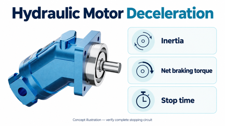
Acceleration torque depends on rotational inertia and the required speed change over time. Add the torque needed to overcome the load during acceleration rather than treating acceleration as free. Repeated starts may also create a thermal duty that a steady-running calculation misses. Request a review using the actual cutter inertia and intended start frequency.
Review impacts and overrunning behavior
A rotating cutter stores kinetic energy. If supply flow is reduced or blocked, the rotor may continue driving the motor as a pump. The resulting pressure and makeup-flow requirements depend on the circuit. A relief setting by itself does not establish a controlled or safe stopping process. Circuit designers must consider the energy path, suction conditions, and component limits during coast-down.
Do not prescribe a generic cross-port valve arrangement from a photograph. The attachment may already incorporate protection, and incorrect additions can change stopping distance, create pressure trapping, or interfere with the carrier controls. Obtain the schematic and have a qualified designer verify pressure relief, makeup provisions, and any anti-cavitation function for the actual direction of rotation and load.
A sudden jam is different from an ordinary coast-down. Mechanical shock, pressure rise, and reaction loads may dominate. The blade, hub, coupling, motor mount, and protective circuit must be assessed together. Never use a jam test as an informal way to discover a motor’s unknown limits.
Match shaft and bearing loads to the real mounting
A motor capable of producing the required hydraulic torque may still be unsuitable for directly carrying the cutter assembly. Blade weight, imbalance, belt tension, coupling alignment, impact, and overhung distance can impose radial and axial loads. These require the exact shaft, bearing, and mounting data rather than an assumption based on motor size or a four-bolt flange.
Confirm whether the attachment uses an independent bearing housing. Where it does, identify how torque is transmitted and how misalignment is controlled. Where the motor supports an external load, submit the load direction, magnitude, speed, duty, and distance from the mounting face for manufacturer review. A torque calculation cannot substitute for this bearing-load assessment.
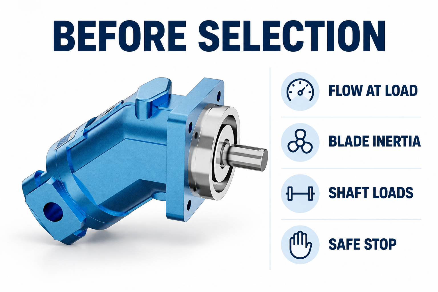
The reference A2FM exterior used in this guide identifies a real catalog motor. It does not prove brush-cutter approval, shaft-load capacity, a particular rotation option, or compatibility with an existing attachment. Obtain the complete order code and dimensional drawing before comparing replacement interfaces.
Use a selection review table
The following is a qualitative engineering checklist. It contains no product ratings. The hydraulic relationships come from standard fluid-power teaching; all acceptance limits must come from the actual carrier, cutter, and ordered motor documents.
| Review item | Evidence to collect | Decision it supports |
|---|---|---|
| Working speed | Cutter-approved rpm and flow at load | Displacement screening and overspeed prevention |
| Cutting torque | Load estimate and motor pressure difference | Sustained operating-point review |
| Startup | Rotor inertia, acceleration time, starting data | Starting torque and repeated-start duty |
| Coast-down | Circuit schematic and stored-energy assessment | Makeup flow and pressure-control review |
| Shaft loading | Load direction, overhang, bearing arrangement | Direct-drive or separate-support assessment |
| Thermal duty | Oil temperature and repeated operating cycle | Cooling and continuous-operation review |
Use the table to identify missing evidence before requesting a quotation. A supplier can evaluate a clearly bounded requirement more reliably than a request based only on motor displacement and carrier horsepower. Keep assumptions visible so that a provisional selection is not mistaken for an approved design.
Validate with a controlled commissioning plan
Commissioning should follow the attachment and carrier manufacturers’ procedures, with guards installed, personnel excluded from the hazard area, and instruments selected for the expected hydraulic conditions. Establish how unexpected speed, pressure, vibration, temperature, or leakage will trigger a stop. Do not approach a rotating assembly to inspect a suspected problem.
Begin with documented setup checks and prescribed lubrication or filling requirements. Progress through permitted operating conditions while recording motor-port pressures, speed, supply flow where available, oil temperature, and relevant case-drain observations. Record the duty duration and temperature at each observation. A brief cold run cannot establish continuous hot-duty suitability.
Before inspection or adjustment, isolate energy and account for residual pressure and continued rotation. NIOSH hazardous-energy guidance supports a formal isolation procedure. Switching off the command does not demonstrate that the blade has stopped or that trapped hydraulic energy has dissipated. Verify the actual safe condition using the approved procedure.
Prepare a quotation request that can be reviewed
Include carrier details, attachment model, complete existing motor code if replacing one, required direction, target speed, measured flow, motor-port pressure range, return and case conditions, oil data, mounting dimensions, shaft interface, external loads, inertia, and the proposed duty cycle. Attach the schematic and drawings rather than asking the supplier to reconstruct the assembly from one photograph.
Ask which assumptions remain provisional and what operating limitations or commissioning checks apply. Keep the response with the equipment record. If a candidate fails the shaft-load or stopping review, return to the assembly design instead of simply raising pressure or choosing a larger displacement. Hydraulic compatibility is only one part of safe cutter-drive selection.
Frequently asked questions
Can I select a brush-cutter motor from carrier flow alone?
No. Flow helps estimate speed after displacement and leakage are considered, but torque, available pressure difference, shaft loads, stopping energy, lubrication, and thermal duty also matter. Use measured attachment flow and the cutter’s approved speed range.
Does a bigger displacement always improve cutting?
A larger displacement increases theoretical torque at the same pressure difference but reduces speed at the same flow. If blade speed falls below the attachment’s intended operating range, the result may be unsuitable even though the torque calculation rises.
Can the motor shaft support the blade assembly directly?
Only when the exact motor’s permitted radial and axial loads, overhang, speed, and duty support that arrangement. Some assemblies require separate bearings. A flange photograph and a torque rating do not establish this suitability.
Will a relief valve make coast-down safe?
A relief valve can limit pressure under specified conditions, but it does not by itself establish stopping time, makeup flow, cavitation protection, or mechanical safety. Review the complete circuit and stored rotational energy with the attachment manufacturer or designer.
What should be checked before replacing an existing motor?
Preserve the complete code, dimensional drawing, direction, displacement, pressure and speed limits, shaft and flange details, drainage requirements, external loads, and protective circuit. Verify the proposed replacement against the attachment’s documented requirements before installation.
Product and related engineering resources
The Fixed Displacement Motor A2FM catalog exterior is used as the real product reference in these explanatory images. It does not establish the approved service method, optional construction, or operating limits for an individual order. Confirm the complete code and its documentation. Related resources: Fixed Displacement Motor A2FM, hydraulic motor range, Hydraulic Motor for Augers: Torque Spikes and Shock Protection, Radial Piston Motor Working Principle: Torque at Low Speed.
Sources and limits of this guide
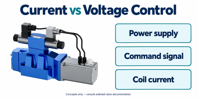
University teaching supports physical and fluid-power principles; NIOSH supports hazardous-energy precautions. Calculations are hypothetical, not Prance ratings. The TI document, where linked, supports current-regulation principles only and is not a recommendation to use that circuit or its settings with the illustrated valve. No curve, pinout, attachment approval or model-specific frequency is inferred from the catalog exterior.
- UNSW Physics: rotational inertia, torque and kinetic energy
- NPTEL: Industrial Oil Hydraulics and Pneumatics
- NIOSH: hazardous-energy injury prevention
University lesson: operating principles
NPTEL-NOC IITM presents 6.3 – Hydraulic Motors. The lesson supports the hydraulic motor operating principles; cutter-specific inertia and stopping acceptance remain separate engineering checks used in this discussion; it is not a model-specific performance or installation approval.