شركة ونزهو برانس للمعدات الهيدروليكية المحدودة

ضغط مضخة السيرفو غير كافٍ: فصل الأمر عن الشوط
Insufficient hydraulic pump servo pressure can prevent a variable-displacement pump from reaching or holding the requested stroke even when its command appears correct. Diagnose the control chain in order: actual command, available control supply, pressure difference across the servo and resulting displacement. A normal charge-pressure reading in neutral does not establish sufficient control margin under load. Conversely, reduced pump stroke can be an intended pressure-limiting response. Identify the complete control configuration and its approved test conditions before adjusting relief settings or replacing the rotating group.
Separate a missing command from a missing hydraulic response
An operator can request more output while the pump receives a limited or incorrect command. A display may show demand rather than the current, pilot pressure or linkage position actually delivered to the control. Begin by identifying what the machine displays and what the pump requires.
For an electrical control, the relevant evidence may include a controller status, enable condition and measured coil current using the specified method. For a hydraulic control, it may include the signal pressures and their references. For a mechanical control, linkage travel and return behavior matter. There is no universal voltage or pilot pressure that proves every variable pump is commanded correctly.
Do not change several stages at once. If a command is wrong, correct its confirmed cause before interpreting an incomplete displacement response. A pump control supplied with the wrong signal can imitate an internal hydraulic fault. Preserve the original command and response record so a subsequent improvement can be attributed to a specific correction.
Understand the difference between supply pressure and servo differential
In a double-acting servo arrangement, pressures on opposite sides influence the force that positions the swashplate. For equal effective piston areas, the pressure difference contributes to net hydraulic force. Available force also has to be considered with springs, friction, feedback and forces associated with the rotating assembly.
As a simplified teaching example, two hypothetical servo chambers at 20 and 18 bar have a difference of 2 bar. Raising both by 5 bar produces 25 and 23 bar, still a 2-bar difference. With an assumed equal effective area of 5 square centimeters, 2 bar corresponds to 100 newtons of differential hydraulic force. The example omits other forces and is not a pump setting, minimum requirement or AA4VG specification.
A single supply-pressure number therefore cannot establish the commanded positioning force. Nor can one chamber’s gauge reading establish the opposite chamber’s condition. Use the exact control schematic to identify where supply, regulated output and return are measured. An unequal-area actuator or a different architecture requires its own force interpretation.
Check control supply in the condition where stroke is lost
A charge circuit can provide adequate pressure at neutral yet fail to maintain the control requirement during a particular load event. Flow demand, leakage, supply restriction and prime-mover speed can change between those states. The relevant comparison is synchronized with the complaint, within an approved test arrangement.
The Danfoss H1T reference manual distinguishes minimum loop-charge requirements from control requirements, which depend on operating conditions. It also describes control behavior separately from main-loop pressure. That is a useful diagnostic distinction, but its numerical requirements and service procedures belong to the named reference units. They cannot be transferred to a Prance AA4VG control.
Record whether the supply falls before or after displacement changes. A pressure collapse that precedes reduced stroke points toward a different sequence from a pressure change after a protection function destrokes the pump. Without a common timeline, two correct readings can still support the wrong causal conclusion.
Examine supply and return paths before condemning the servo
The servo needs a usable pressure difference, which depends on both sides of its circuit. A restricted supply, contaminated control passage or unsuitable return condition can reduce that difference. Increasing supply pressure without understanding the path can hide the symptom and exceed another component’s limit.
Use maintenance history to target the inspection. A recently changed filter, hose, control cover or fitting may be more informative than the pump’s total running hours. Confirm that installed parts match the controlled drawing. An orifice that looks clean externally may still require the manufacturer’s inspection method; do not enlarge or remove it as an informal response test.
All opening, cleaning and component replacement require isolation and the specified cleanliness controls. Never crack a live pilot line to see whether pressure is present. A small line can carry hazardous stored energy. If internal examination is necessary, follow the authorized service boundary rather than applying disassembly steps from a similar-looking pump.
Recognize intentional destroking before calling it a failure
Some closed-circuit controls deliberately reduce displacement when a pressure-limiting condition is reached. Reduced stroke at that moment can be the expected protective response. A service complaint must distinguish inability to reach stroke from a command that is being intentionally overridden by a higher-priority function.
Compare the displacement response with loop differential pressure, relevant limit status and the approved settings. A repeatable reduction at the specified protection condition deserves investigation of the load and settings before a servo repair. A reduction far below the expected condition may indicate a supply, control or measurement issue, but it still needs a documented test.
Do not raise pressure limits simply to force the pump to hold stroke. The pump, motor, hoses and driven machine all have constraints. A change that restores motion can create an overload elsewhere. The correct goal is the specified response under the intended duty, not maximum stroke under every load.
Use a control-chain diagnostic table
This table is a qualitative decision aid. It provides no pressure setting, coil-current threshold or adjustment direction for an unconfirmed control version.
| Observation during an approved test | التمييز الأول الذي يجب إجراؤه | Next useful evidence |
|---|---|---|
| Operator requests output but actual input remains limited | Command path versus hydraulic response | Measured pump input and controller enable/limit state |
| Input is correct but control supply falls under load | Supply capacity versus a downstream demand or leakage | Synchronized supply, speed and loop-condition record |
| Supply remains available but servo differential is small | Control metering, opposing pressure or internal leakage | Both servo pressures with the correct references |
| Servo differential develops but stroke does not follow | Position feedback, mechanical limitation or actuator condition | Approved displacement evidence and control-specific inspection |
| Stroke reduces at a known limiting condition | Intended protection versus an abnormal loss of response | Exact limiter specification and loop differential |
| One direction behaves differently | Direction-specific command, control path or installed option | Comparable forward/reverse data under the approved duty |
A row identifies a question, not a final component diagnosis. Multiple faults can occur together. For instance, an incorrect command and contaminated control path can both reduce response. Confirm each stage before moving to the next so replacing one part does not leave a second cause unresolved.
Confirm how displacement is being inferred
Reduced machine speed alone does not prove reduced pump displacement. Motor displacement, mechanical gearing, bypass leakage and load can affect output speed. Even measured delivered flow depends on shaft speed and volumetric losses, so it needs interpretation.
Where permitted, use the manufacturer’s direct position indication or validated measurement method. If displacement is inferred from flow and speed, state the assumptions and operating conditions. A warm, heavily loaded pump may deliver less net flow than the same geometric displacement under a different condition because leakage changes.
A pressure differential across the servo indicates hydraulic actuation conditions; it is not by itself a calibrated swashplate-angle measurement. The strongest diagnosis pairs approved displacement evidence with the control input and pressures. That combination helps separate inadequate actuation from an incorrect assumption about the resulting output.

Review the actual AA4VG control before ordering parts
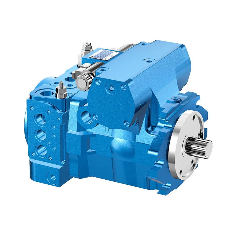
Prance’s AA4VG product entry provides a relevant closed-loop variable-displacement pump family. Its original photographs support exterior identification and a procurement discussion. They do not establish the exact servo arrangement, control supply option, port naming or pressure requirement of every configuration.
Provide the complete code, machine schematic and the control-chain evidence when requesting a replacement review. Include fluid condition, operating temperature, shaft speed, the direction that fails and the duty where stroke is lost. Ask for the offered control’s documented signal requirements and acceptance method. A matching flange and shaft do not establish equivalent control behavior.
After a confirmed repair, repeat the same permitted operating comparison. Verify response from both directions where relevant, including the conditions that exposed the problem. Record the unchanged protection settings and the accepted output. This closes the diagnosis with evidence that the intended control function was restored, rather than a note that a replacement part was fitted.

الأسئلة الشائعة
هل يستبعد ضغط الشحن الطبيعي في الوضع المحايد مشكلة في التحكم أو الإمداد؟
No. Supply and control demand can change under load or during a command transition. Compare the approved supply measurement with the event where stroke is lost and use the exact model’s control requirements rather than a neutral reading alone.
هل يمكن أن يثبت قياس ضغط سيرفو واحد قوة موضع كافية؟
Not for a double-acting arrangement. The opposing chamber pressure and actuator geometry matter, together with springs and other forces. Use the documented pressure references and measurement points for the selected control.
Should the charge relief be increased until the pump strokes fully?
No. First establish whether the command, supply, metering paths and protection functions operate as specified. Raising pressure can hide a restriction or leakage and exceed component limits. Any adjustment needs the exact approved procedure and acceptance criteria.
Why might the pump lose stroke only at high loop pressure?
Possible explanations include intended pressure limiting, insufficient control margin under the actual duty or increased leakage. The symptom does not identify one cause. Compare command, loop differential, supply and servo response on the same timeline.
Is this the same problem as neutral creep?
No. Neutral creep concerns unwanted motion near a neutral demand. This guide concerns failure to achieve or retain requested displacement. Some control components may be shared, but the operating state, evidence and acceptance tests differ.
موارد المنتج والهندسة ذات الصلة
مضخة مكبس ذات دائرة مغلقة متغيرة الإزاحة AA4VG, نطاق منتجات المضخة الهيدروليكية, Hydrostatic Neutral Creep: Separating Pump Offset from Load Effects, ضغط الشحن المغلق: ما يمده وكيفية تشخيص الفقدان. تأكيد رمز المنتج الكامل ومتطلبات التطبيق عند طلب مراجعة التكوين.
Technical references
- Danfoss H1T service manual: reference control and measurement architecture, not AA4VG specifications
- Danfoss: Transmission Circuit Recommendations, reference bypass and charge circuit principles
- NIOSH: Preventing Deaths from Uncontrolled Hazardous Energy
تعلم إضافي: مضخات هيدروليكية
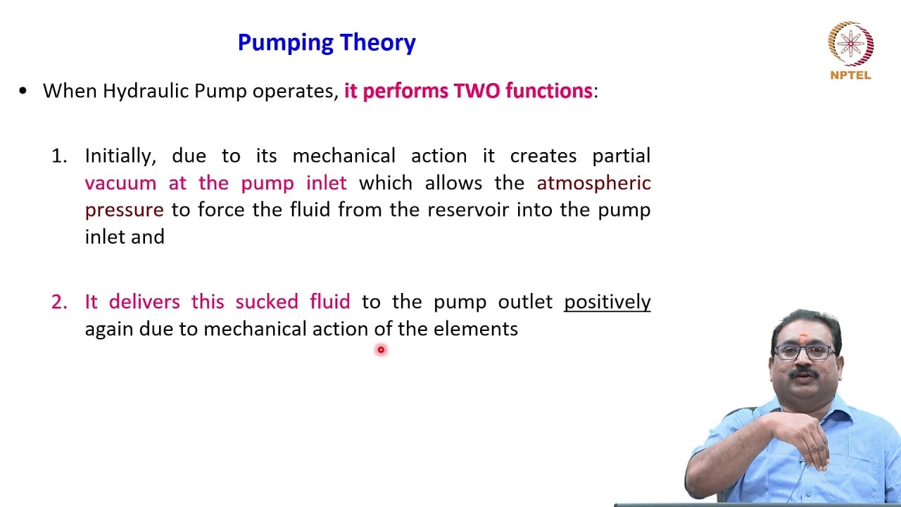
3.2 – Hydraulic Pumps by NPTEL-NOC IITM provides background on pump operating principles. Pump fundamentals explain displacement and flow. This lecture does not demonstrate the diagnostic or recovery procedure described here. It supplements the component fundamentals; it is not a test procedure for the complete circuit discussed above.