شركة ونزهو برانس للمعدات الهيدروليكية المحدودة

Trapped Volume in Gear Pumps: How Relief Grooves Control Compression
Hydraulic gear pump trapped volume is the small pocket of oil temporarily enclosed between meshing teeth and the adjacent sealing surfaces. As the gears rotate, that pocket can shrink and then expand. Without a suitable connection to another fluid space, compression can raise local pressure, while expansion can lower it. Relief grooves provide carefully timed communication that moderates these changes. They are internal geometric features, not the adjustable system relief valve. Their shape, position, and interaction with clearances must be evaluated for the specific external gear-pump design.
Follow the oil through one gear-mesh cycle
An external gear pump transports fluid around the outside of the gears, in spaces bounded by the teeth and casing. Near the inlet, teeth leaving mesh create increasing space. Near the discharge, teeth entering mesh reduce the available space. The meshing region separates the high-pressure and low-pressure sides while the outer tooth spaces carry the useful displacement.
The trapped pocket considered here is different from those outer transport spaces. Depending on tooth geometry, more than one pair of teeth can be in contact during part of the cycle. A small enclosed region can then form between the contact lines. Its volume changes as the contact points move.
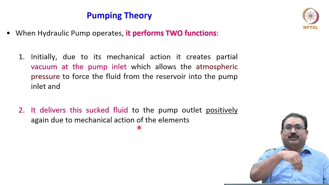
NPTEL’s gear-pump lesson explains the basic inlet, transport, and discharge sequence. University research on external gear-pump suction and meshing adds the more detailed discussion of enclosed volumes and relief-groove communication. Neither source provides the unpublished internal geometry of the Prance HDH series.
Why compression produces a local pressure event
Oil has finite compressibility. Reducing the volume of a genuinely isolated, liquid-filled pocket requires a pressure increase. The actual pressure depends on the changing pocket volume, fluid properties, leakage paths, entrained gas, and connections available at that angular position. It cannot be calculated reliably from discharge pressure alone.
For a simplified, single-phase, closed pocket with a small volume change, the relationship can be expressed as pressure change approximately equal to effective bulk modulus multiplied by fractional volume reduction. This is a mechanism explanation, not a pump-rating formula. Real leakage and communication can substantially change the result.
Do not insert a general handbook bulk modulus into this relationship and advertise the result as an HDH pressure spike. Effective compressibility depends on fluid condition and gas content, and the actual pocket geometry is required. A model needs verified inputs before it can support a numerical design conclusion.
Why expansion also needs a flow path
After the minimum volume, continued rotation may increase the enclosed space. If replacement fluid cannot enter promptly, pressure can fall. Gas release or vapor formation may then affect the pocket contents and the subsequent pressure recovery. The behavior depends on fluid state and the pressure history, not just the nominal inlet condition.
The engineering task is therefore two-sided: provide appropriate escape during compression and appropriate filling during expansion. A feature that simply removes restriction everywhere can create an unwanted connection between high and low pressure. Useful relief requires timing as well as area.
This also explains why an apparently small change in a side plate can matter. A groove controls when communication starts, how long it remains available, and how much flow can pass. Its effect must be considered alongside the complete mesh cycle.
What relief grooves actually control
A relief groove is typically formed in a surface adjacent to the gear faces, although the implementation varies with construction. Its purpose is to connect the changing pocket to an appropriate pressure region during the intended portion of rotation. The name describes a local hydraulic function, not a universal shape or size.
Research models compare pocket volume, groove opening, pressure history, leakage, and delivered flow. These quantities interact. Changing a groove can reduce one local pressure event while increasing another loss or altering ripple elsewhere in the cycle. A successful design balances several effects rather than maximizing groove size.
A purchased replacement plate should therefore match the approved pump configuration. A similar outline is insufficient. Port location, handedness, gear geometry, clearances, and any pressure-balancing passages may be relevant to compatibility.
Distinguish three different pressure-related features
| الميزة | Where it acts | Main engineering question | ما لا يمكن أن يثبته بمفرده |
|---|---|---|---|
| Trapped-volume relief groove | Near the gear-meshing pocket | Is pocket communication timed appropriately? | Overall machine pressure protection |
| System pressure relief valve | In the hydraulic circuit | Is maximum circuit pressure controlled for the duty? | The instantaneous pressure inside an isolated tooth pocket |
| Pressure-balanced side plate | At a sealing or bearing-related interface | Are clearance and loading controlled over the working range? | Correct relief-groove timing for another plate design |
| Inlet passage | Upstream and at filling chambers | Can fluid reach the pump within its inlet limits? | Absence of every local low-pressure event |
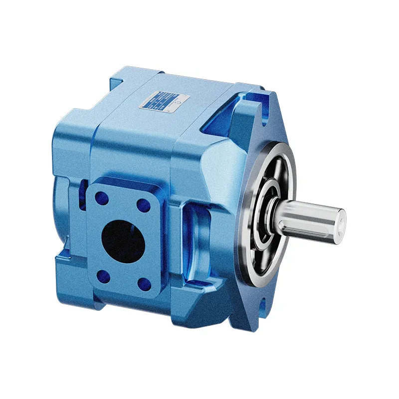
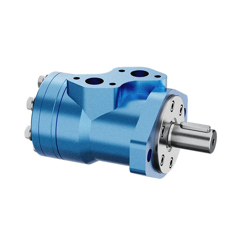
The distinctions follow the fluid spaces involved. They are not interchangeability claims or a diagnosis of any specific pump shown in the photographs.
Separate trapped-volume effects from ordinary flow ripple
External gear pumps deliver a periodically varying flow because the displacement process changes with angular position. Trapped-volume compression, expansion, leakage, and groove communication can influence that waveform. They are related mechanisms, but they should not be treated as identical terms.
cURL Too many subrequests by single Worker invocation. To configure this limit, refer to https://developers.cloudflare.com/workers/wrangler/configuration/#limits.
cURL Too many subrequests by single Worker invocation. To configure this limit, refer to https://developers.cloudflare.com/workers/wrangler/configuration/#limits.
cURL Too many subrequests by single Worker invocation. To configure this limit, refer to https://developers.cloudflare.com/workers/wrangler/configuration/#limits
cURL Too many subrequests by single Worker invocation. To configure this limit, refer to https://developers.cloudflare.com/workers/wrangler/configuration/#limits.
cURL Too many subrequests by single Worker invocation. To configure this limit, refer to https://developers.cloudflare.com/workers/wrangler/configuration/#limits.
cURL Too many subrequests by single Worker invocation. To configure this limit, refer to https://developers.cloudflare.com/workers/wrangler/configuration/#limits.

cURL Too many subrequests by single Worker invocation. To configure this limit, refer to https://developers.cloudflare.com/workers/wrangler/configuration/#limits
cURL Too many subrequests by single Worker invocation. To configure this limit, refer to https://developers.cloudflare.com/workers/wrangler/configuration/#limits.
Photograph removed parts before cleaning, preserve their orientation, and retain the work history. Marks around a groove or sealing face may be relevant, but wear patterns should be interpreted with the design drawing and dimensional checks. A photograph cannot establish the original machining tolerance.
Do not enlarge, deepen, or add a groove as an informal noise treatment. Such a change can alter high-to-low pressure leakage, plate loading, structural margins, and timing. Any redesign belongs in a controlled engineering process with verified geometry and performance testing.
What a useful design validation should include
For an engineering comparison, define the operating envelope before choosing a model. Include speed, inlet condition, outlet pressure, viscosity or temperature, rotation, and fluid aeration assumptions. State how the model handles compressibility, leakage, and gas or vapor formation. These choices strongly affect the pressure history of a small changing pocket.
Validation should compare measured and predicted behavior under the same conditions. Average flow alone may not validate the predicted local pressure event. Where direct pocket measurement is impractical, document the limitations of the available signals and the confidence appropriate to the conclusion.
A study of one laboratory pump can explain mechanisms and modeling methods. It cannot provide an operating rating, noise guarantee, or optimal groove geometry for another manufacturer’s product. Keep published research findings separate from product-specific acceptance evidence.
Specify a replacement or inquiry clearly
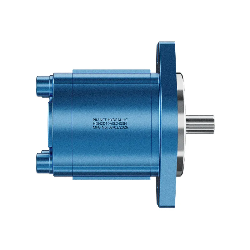
When discussing an HDH external gear pump with Prance, provide the full product code, rotation, displacement requirement, speed range, pressure duty, fluid, temperature range, and connection arrangement. If the inquiry follows a noise complaint, include the inlet measurements, operating sequence, and any parts changed before the problem appeared.
Ask for confirmation of the approved assembly and any serviceable replacement components. If internal groove geometry is not published, request a performance review rather than inventing dimensions from an exterior photograph. The original product photographs identify the relevant product family; they do not show a verified cross-section.
A practical acceptance plan checks required flow, pressure behavior, temperature, leakage, and noise under repeatable machine conditions. Record the baseline and the replacement result using the same instruments and operating points. This creates evidence for the purchasing decision without promising that one internal feature explains every symptom.
الأسئلة الشائعة
Is trapped oil the same as the oil carried around the gears?
No. The useful displacement travels mainly in tooth spaces around the casing. The trapped pocket discussed here forms temporarily within the meshing region under the relevant tooth-contact geometry. Its changing volume can create a separate local pressure event.
Does the system relief valve protect every trapped pocket?
Not necessarily. An isolated pocket may not communicate directly with the circuit while it is enclosed. The circuit relief valve and internal groove timing perform different functions, and both must be appropriate to the design.
Will a larger relief groove always make the pump quieter?
No. Increasing communication can change leakage, delivered flow, pressure transitions, and efficiency. Groove geometry and timing require a complete design review rather than a larger-is-better rule.
Can noise confirm that a relief groove is damaged?
Noise alone cannot locate the cause. Inlet restriction, aeration, mounting, circuit resonance, and worn components can produce similar complaints. Use operating measurements and repair history before opening the pump.
Can published groove dimensions be copied into another pump?
No. Dimensions depend on tooth geometry, rotation, port arrangement, clearances, and other design features. Published research can guide understanding, but the approved component drawing controls compatibility and any modification.
موارد المنتج والهندسة ذات الصلة
مضخة تروس خارجية HDH, نطاق منتجات المضخة الهيدروليكية, تذبذب ضغط مضخة التروس الهيدروليكية: تأثير عدد الأسنان والضوضاء, صمامات عدم الرجوع عند مخرج المضخة الهيدروليكية: منع التدفق العكسي والعزل عند إيقاف التشغيل. تأكيد رمز المنتج الكامل ومتطلبات التطبيق عند طلب مراجعة التكوين.
Technical references
- NPTEL: external gear pumps
- Universitat Politecnica de Catalunya: Analysis of the Suction Chamber of External Gear Pumps
تعلم إضافي: مضخات هيدروليكية
3.2 – Hydraulic Pumps by NPTEL-NOC IITM provides background on pump operating principles. Use this lesson for the energy-conversion fundamentals. Seal leakage, relief-groove timing and spline lubrication require the specific component documentation, not inference from a general lesson. It supplements the component fundamentals; it is not a test procedure for the complete circuit discussed above.