شركة ونزهو برانس للمعدات الهيدروليكية المحدودة

صمامات تقليل وتخفيف ثلاثية الاتجاهات: للتحكم في الضغط من كلا الاتجاهين
A hydraulic pressure reducing relieving valve controls a lower-pressure branch and provides a path for excess downstream pressure to escape. A reducing-only valve mainly restricts incoming supply; it cannot automatically be assumed to discharge pressure created by an external load or trapped-fluid heating. Choose the function from the complete circuit, including how pressure can rise after the supply passage closes. Confirm the exact valve symbol, port assignments, relieving capacity, and return-pressure limits. A small pilot drain is not automatically a full-flow relief connection, and a pressure-reducing function is not a substitute for every required safety or load-holding device.
Start with the downstream pressure source
A branch may need lower pressure than the main supply because it operates a clamp, pilot circuit, auxiliary actuator, or another component with a different requirement. A reducing valve senses the controlled downstream pressure and throttles supply as that pressure approaches its setting. This is different from a main relief valve that responds to pressure on its inlet side by diverting flow.
Now ask what happens after the reducing passage closes. An external force may push an actuator, another circuit may feed the branch through a connection, or trapped oil may warm. In those cases the source of the pressure increase is downstream of the closed supply path. Simply closing that path further cannot remove the trapped volume or release the added pressure. That is the operating situation a reducing/relieving arrangement is intended to address, within its documented capacity.
Follow the three functional states
Below the controlled pressure, the reducing path admits fluid from the high-pressure supply to the branch. Near the control point, the valve meters that incoming flow to balance demand and maintain the reduced pressure within its performance characteristics. If downstream pressure rises sufficiently above the regulating condition, a reducing/relieving design opens a separate path from the controlled branch toward the designated return port.
The transition is not an ideal switch at one mathematically exact pressure. Spring characteristics, spool overlap, hysteresis, flow forces, pilot arrangement, and operating flow can affect the actual pressure-flow response. Use the particular valve’s reducing and relieving curves. A label showing only the adjustment range does not establish the pressure that will occur during a high-flow relieving event.
For that reason, compare the expected downstream event with the relieving side of the documentation rather than checking only the normal supply rating. A valve capable of passing the required reducing flow does not necessarily have the same acceptable performance when fluid flows out of the branch. Port descriptions and performance curves must establish both duties.
Distinguish a drain from a working return
Some pressure controls use a drain to keep their spring chamber or pilot stage referenced to a specified pressure. That drain may carry only leakage or pilot flow. A reducing/relieving valve also needs a route capable of carrying the intended relieving flow. Depending on the design, functions may share a port or use separate passages. The symbol and manufacturer instructions establish the arrangement.
Do not connect an unverified small drain hose and assume it can discharge the full actuator flow. Restriction in the relieving return can raise downstream pressure and change the regulating behavior. Return back pressure may also change the pressure reference, depending on the valve design. Check maximum pressure, flow capacity, routing, and any required dedicated connection for each port separately.
Compare the functions before selecting a replacement
| Circuit requirement | Reducing-only function | Reducing/relieving function | التحقق مطلوب |
|---|---|---|---|
| Supply a lower-pressure branch | Meters incoming supply | Meters incoming supply | Required reducing flow and pressure-flow behavior |
| Handle pressure generated in the branch | Cannot be assumed to discharge it | Provides a documented relieving path | Cause, duration, and amount of relieving flow |
| Reference a pilot or spring chamber | May require a drain | May share or separate drain and return duties | Exact port diagram and back-pressure sensitivity |
| Reverse flow through the branch | Depends on the design | Also depends on the design | Check-valve options and reverse-flow limits |
| Prevent hazardous load movement | Not established by reducing alone | Not established by relieving alone | Separate machine risk review and load control |
| Replace an existing valve | Matching adjustment range is insufficient | Matching adjustment range is insufficient | Function, interfaces, capacity, and full ordering code |
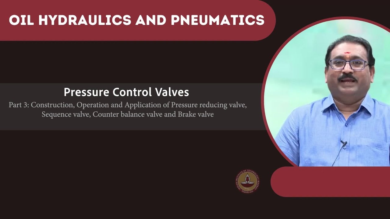
This is a qualitative selection table, not a product parameter sheet. The NPTEL pressure-control lessons distinguish downstream regulation from upstream pressure relief. Specific reducing/relieving behavior must be checked against the selected manufacturer’s technical information. None of these functions is assigned to a pictured directional valve merely because it belongs to the same hydraulic system.
Estimate the relieving duty from the physical event
If an actuator is being forced backward, the oil leaving its controlled chamber can be related to effective piston area and imposed velocity. That flow can be much larger than pilot leakage. Establish the actual chamber, motion direction, and any other flow path before estimating the required valve duty. Differential cylinder areas can produce pressure relationships that a simple pressure-setting comparison misses.
Thermal expansion of an isolated volume is a different duty from sustained actuator motion. It may involve little displaced volume but still create an unacceptable pressure rise if no suitable path exists. Do not size every event as a continuous full-flow event, and do not dismiss all events as minor thermal relief. Identify the credible cause first, then use its flow, duration, pressure, and temperature conditions for selection.
A main system relief upstream of a closed reducing valve does not necessarily protect the isolated downstream volume. Trace a continuous hydraulic path from the threatened volume to the protective device in every relevant valve position. If that path is blocked, the upstream device’s presence alone does not resolve the branch-pressure question.
Check the pressure reference under real return conditions
A return connection that looks satisfactory during idle operation can experience a pressure increase when another function sends flow through the same manifold or filter. If the pressure control references that return, the controlled branch may behave differently even though its adjustment screw has not moved. Record branch pressure and the relevant return or drain pressure during the same event.
Keep the distinction between gauge pressure and pressure difference clear. A spring-balanced mechanism responds to forces at its effective areas. The application documentation determines which pressure contributes to that balance. Do not apply a universal one-to-one correction to every valve, because internally balanced, externally drained, direct-acting, and pilot-operated arrangements can differ.
Relate the control to the actual Prance product
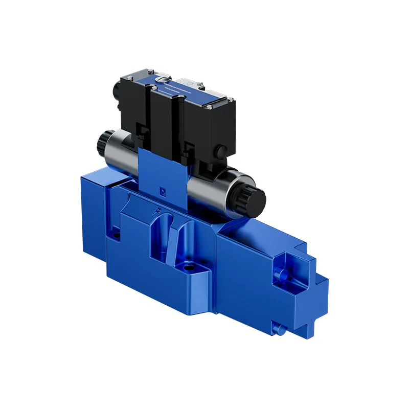
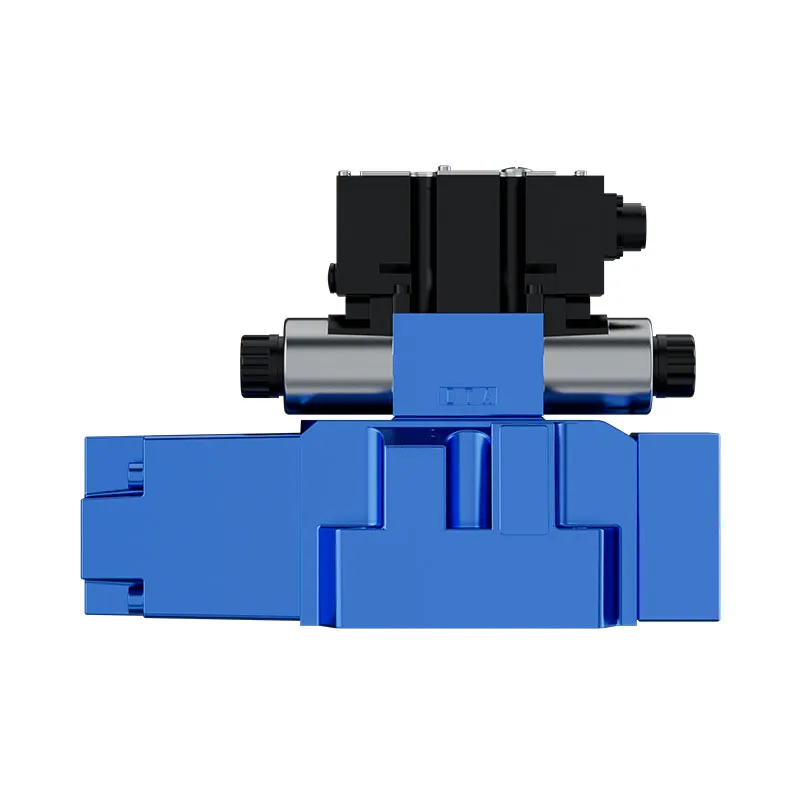
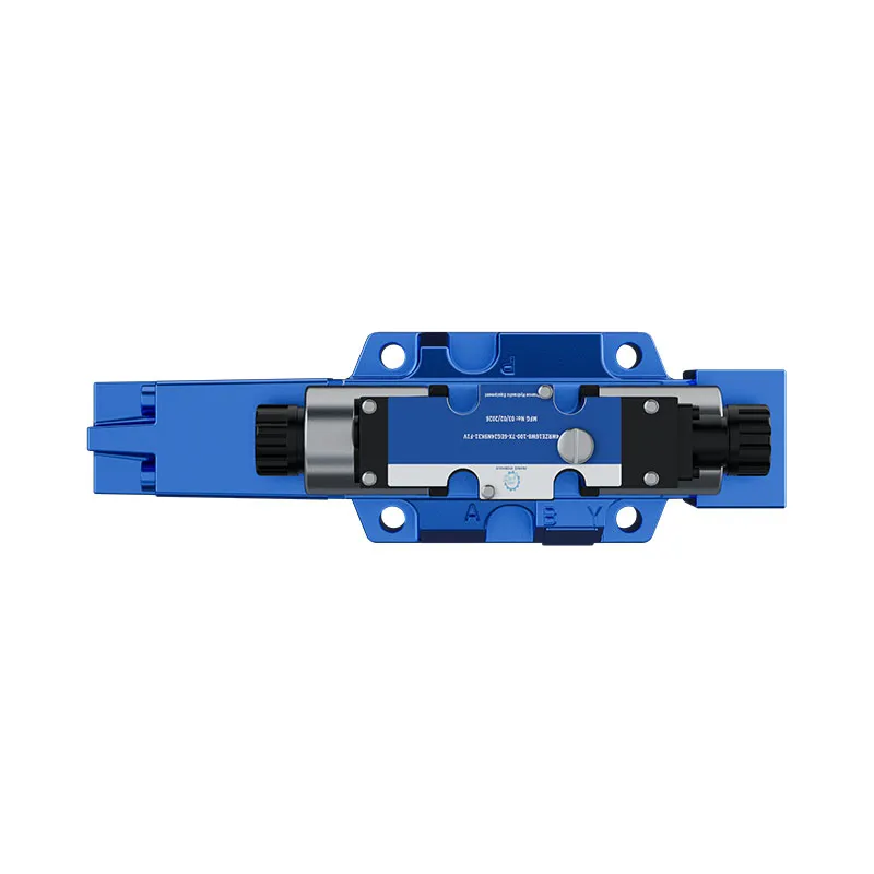
The website offers a Pilot Proportional Valve for Press 4WRZE. Its published description identifies a pilot-operated proportional directional-control product associated with controlling direction and flow. The original exterior photographs illustrate that product family in a broader hydraulic-control discussion. They do not show or prove that this valve contains a reducing/relieving stage.
A press circuit may require a separate branch-pressure control in addition to its directional valve. Determine that need from the circuit and the load, not from the appearance of the directional valve. For a quotation, identify which function is required from each component. Ask for the complete code, applicable hydraulic symbol, installation interface, and documentation establishing the exact pressure-control duty. Do not substitute a 4WRZE photograph or name for the missing specification of another valve.
Commission without masking the cause
قبل إجراء الضبط، تأكد من هوية المنافذ، ومسارات الأنابيب، ومدى ملاءمة المائع، وحالة بدء التشغيل المعتمدة من الشركة المصنّعة. استخدم إجراء التشغيل الأولي الآمن الخاص بالماكينة وأجهزة القياس المناسبة. سجّل ضغط التغذية، والضغط المتحكَّم فيه، وضغط الرجوع، ودرجة الحرارة، وحالة التدفق، وظروف الضبط. ابدأ بظروف الاختبار المسموح بها بدلاً من إجبار المشغّل على العمل مقابل حاجز ميكانيكي لإنشاء مصدر ضغط مرتجل.
إذا كان ضغط الفرع مرتفعاً للغاية، فتحقق مما إذا كان تنظيم ضغط التغذية معطلاً أم أن ضغط المصب يتولد بشكل مستقل. فكلتا المشكلتين تتطلبان فحوصات مختلفة. قد يستلزم الأمر التحقق من وجود تلوث، أو انسداد في خط التصريف، أو توصيل غير صحيح، أو نطاق تدفق غير مناسب، أو وظيفة غير صحيحة للصمام. إن تدوير برغي الضبط دون تحديد حالة التشغيل قد يؤدي إلى إخفاء الأدلة وإحداث إعداد غير آمن في مرحلة أخرى من دورة التشغيل.
تحديد ما يجب أن يتضمنه مواصفات الشراء
حدد الضغط المخفَّض المطلوب وفقاً لظروف التدفق المحددة، ونطاق ضغط التغذية، ومعدل التدفق أثناء التخفيض، ومعدل التدفق أثناء التنفيس ومدته، ونوع المائع، ودرجة الحرارة، وضغط الرجوع المسموح به. أدرج مصدر الضغط في جهة المصب، ومتطلبات التدفق العكسي، والحالة المطلوبة عند فقدان الطاقة الكهربائية أو الهيدروليكية. وضّح ما إذا كانت أي قيمة ضبط تمثل قيمة اختبار في المصنع أم متطلب قبول بعد التركيب.
اطلب منحنيات أداء تخفيض الضغط والتنفيس، وتحديد وظائف المنافذ، وتعليمات التصريف، وأي معلومات عن تدفق التحكم التجريبي اللازمة لتصميم النظام. حدّد تجويف الخرطوشة أو واجهة التثبيت بشكل منفصل عن الوظيفة الهيدروليكية. فقد يتوافق الصمام من الناحية الميكانيكية مع موضع التركيب، ومع ذلك قد يختلف أداؤه. عندما تعتمد سلامة الأفراد أو تثبيت الأحمال على التحكم في الضغط، يجب على مصمم الماكينة التحقق من البنية الوقائية بدلاً من الاعتماد على وصف عام في كتالوج المنتجات.
يجب أن يثبت اختبار القبول كلاً من التنظيم الطبيعي للضغط وسلوك التنفيس المقصود ضمن الظروف المعتمدة. احتفظ بالإعدادات والقياسات النهائية. افصل مصدر الطاقة، وحرّر الطاقة الهيدروليكية المخزنة، وثبّت الأجزاء التي يحتمل أن تتحرك قبل فك أي وصلة؛ ولا تستخدم مطلقاً وصلة مفكوكة كوسيلة غير رسمية لتخفيف الضغط.
الأسئلة الشائعة
هل صمام تقليل الضغط هو نفسه صمام التخفيف؟
لا. الصمام المخفض ينظم الضغط في المخرج عن طريق التحكم في الإمداد الوارد. الصمام المفرغ يستجيب لضغط مدخله بفتح مسار تصريف. الصمام المخفض/المفرغ يجمع بين تنظيم المخرج ووظيفة تصريف مخرج محددة.
هل يوفر كل صمام تخفيض ثلاثي المنافذ تدفق تخفيف كامل؟
لا. قد يكون الاتصال الثالث عبارة عن تصريف لطرف أو حجرة نابض أو طيار. اقرأ الرمز الهيدروليكي، أوصاف المنافذ، وبيانات الأداء. يجب توثيق تدفق التخفيف والضغط المسموح للعودة بدلاً من استنتاجه من عدد الاتصالات.
هل يمكن لصمام تقليل/تخفيف الضغط أن يحمل حمولة معلقة بأمان؟
لا يمكن استنتاج ذلك من وظيفة التحكم في الضغط الخاصة به. يمكن أن يسمح التخفيف للسوائل بالخروج من حجرة محملة. الحمل المعلق يحتاج إلى مراجعة خاصة بالآلة حول تثبيت الحمل، والإيقاف، والاستجابة للفشل، وأي أجهزة حماية مستقلة مطلوبة.
لماذا يتغير ضغط الفرع عندما تعمل وظيفة أخرى؟
قد يؤثر ضغط خط الرجوع المشترك، أو قيود التغذية، أو تفاعلات التحكم التجريبي، أو تغيرات الأحمال في الفرع. قِس الضغوط ذات الصلة في الوقت نفسه وتتبع مسارات التدفق الفعلية. لا تفترض حدوث انحراف في إعداد الضبط قبل التحقق من ظروف الدائرة الهيدروليكية.
هل الصمام 4WRZE المصور هو صمام تخفيض/تخفيف؟
يحدد الموقع الإلكتروني أنه صمام اتجاه تناسبي يعمل بالطيار. صورته لا تثبت وظيفة تقليل/تخفيف. اختر أي مكون تحكم ضغط منفصل من الوثائق المعتمدة ومتطلبات الدائرة الكاملة.
موارد المنتج والهندسة ذات الصلة
صمام تناسبي مشغل بواسطة الطيار للضغط 4WRZE, نطاق منتجات الصمامات الهيدروليكية, صمامات التحكم الهيدروليكية: الاختلافات بين الاتجاه والضغط والتدفق, تصريف الصمام الداخلي مقابل الخارجي: كيف يغير ضغط الخزان الخلفي التحكم. تأكيد رمز المنتج الكامل ومتطلبات التطبيق عند طلب مراجعة التكوين.
Technical references
- صمام تخفيض الضغط من NPTEL
- صمام تنفيس الضغط من NPTEL
- المعهد الوطني للسلامة والصحة المهنية (NIOSH) – التحكم في مصادر الطاقة الخطرة
درس جامعي: الصمامات الهيدروليكية
5.8 – صمامات التحكم في الضغط بواسطة NPTEL-NOC IITM يوفر خلفية عن مبادئ تشغيل الصمامات. يكمل أساسيات المكونات؛ وهو ليس إجراء اختبار للدائرة الكاملة التي نوقشت أعلاه.