Wenzhou Prance Hydraulic Equipment Co., Ltd

Balanced vs Unbalanced Vane Pump: Force, Flow, and Selection
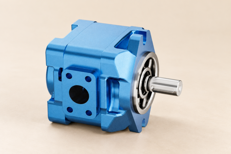
Balanced vane pump vs unbalanced vane pump describes how pressure zones act around the rotor. An unbalanced vane pump normally has one inlet region and one outlet region created by an eccentric rotor and cam ring. Outlet pressure acts predominantly on one side, producing a net radial load on the rotor, shaft, and bearings. A balanced vane pump uses two opposed inlet regions and two opposed outlet regions in a double-lobe cam ring. The opposing pressure forces largely cancel, reducing net radial load. This distinction affects bearing loading, pressure capability, package design, displacement control, and service behavior. It does not by itself establish the exact pump’s pressure, speed, noise, or life.
Shared vane-pump operating principle
Both designs use a rotor with radial slots and vanes that move outward to follow a cam surface. The spaces between adjacent vanes, the rotor, and cam ring form pumping chambers. Where the distance between rotor and cam surface increases, chamber volume expands and draws oil from an inlet port. Where that distance decreases, chamber volume contracts and displaces oil to an outlet port.
Vane contact may be supported by centrifugal force, springs, under-vane pressure, porting, or a combination defined by the design. The cartridge often includes the rotor, vanes, cam ring, and side or pressure plates. These parts work as a clearance-controlled set, so field mixing of visually similar parts can change timing, contact, and leakage.
How an unbalanced vane pump is arranged
In the simplest unbalanced layout, the rotor turns eccentrically inside a circular cam ring. Chamber volume grows through one side of rotation and shrinks through the opposite side. This creates one primary suction arc and one primary discharge arc. Because high pressure occupies one side of the rotor, the resulting hydraulic force has a net radial direction.
The geometry can be useful when variable displacement is required. Moving the cam ring relative to the rotor changes eccentricity, which changes vane stroke and displacement. Reducing eccentricity toward zero reduces displacement; moving through center can reverse the pumping direction in designs intended for that function. Do not assume every unbalanced vane pump has an adjustable ring.
How a balanced vane pump is arranged
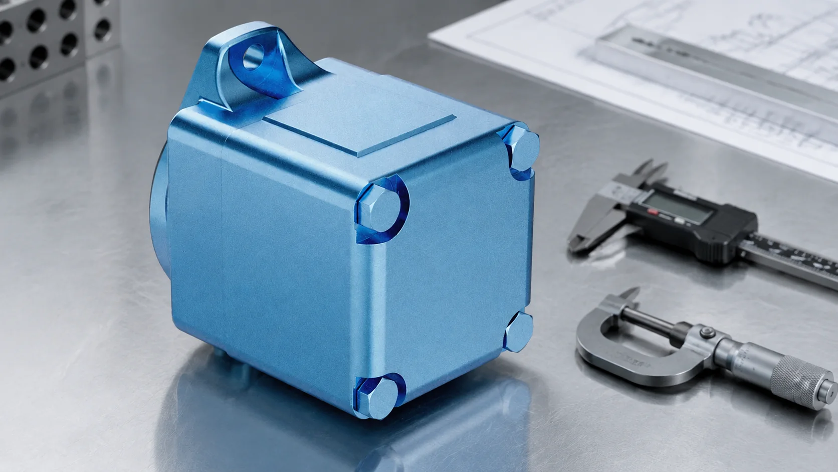
A balanced cam ring has two opposed high points and two opposed low points. During one revolution, each chamber passes through two inlet and two outlet cycles. The outlet zones are positioned opposite one another, so the pressure forces acting on the rotor substantially counterbalance. Bearings still carry mechanical and residual loads, but the major hydraulic radial load is reduced.
This arrangement supports compact fixed-displacement cartridges used in many industrial and mobile circuits. Many balanced vane pumps are fixed displacement because shifting the double-lobe ring does not provide the same simple eccentricity control as a circular ring. Some product families use other methods or specialized geometry, so determine displacement behavior from the data sheet.
Side-by-side engineering comparison
| Factor | Unbalanced vane pump | Balanced vane pump | What to verify |
|---|---|---|---|
| Pumping zones | Usually one inlet and one outlet zone | Two opposed inlet and outlet zones | Port and cam-ring drawing |
| Rotor radial load | Net hydraulic side load remains | Opposed loads largely cancel | Bearing design and pressure rating |
| Displacement control | Eccentric ring can enable variation | Common cartridges are fixed displacement | Exact control architecture |
| Flow events | One pumping cycle per chamber each revolution | Two pumping cycles per chamber each revolution | Ripple and noise data |
| Service focus | Ring position and control mechanism may matter | Cartridge orientation and matched parts matter | Approved assembly procedure |
Why force balance matters
Outlet pressure acting across projected areas creates load. In an unbalanced pump, the pressure distribution is asymmetric, so the shaft and bearings react a substantial radial force. As working pressure rises, that force generally rises. A balanced layout places similar pressure zones on opposite sides, decreasing the resultant force and allowing the designer to allocate bearing capacity differently.
Balanced does not mean load-free. Pressure transitions, port timing, unequal chamber conditions, mechanical drive loads, contamination, misalignment, and transient pressure can still load parts. It also does not mean the unit is dynamically balanced in every vibration sense. The term refers primarily to hydraulic radial-force arrangement.
Pressure, flow, and efficiency limits
A balanced design often supports higher hydraulic pressure than a comparable simple unbalanced design because radial load is reduced. However, do not use that tendency as a rating. Cam-ring contact, vane tip loading, side-plate sealing, shaft torque, housing stiffness, speed, oil film, and duty cycle can become limiting factors. Use continuous, intermittent, and peak ratings for the exact model.
Theoretical flow follows displacement and speed. Actual delivery is reduced by internal leakage. Mechanical friction and leakage together generate heat. Oil that becomes too thin can increase leakage and weaken films; oil that is too thick can increase inlet loss and friction. Compare performance at operating temperature rather than relying only on nominal oil grade.
A University of Minnesota engineering thesis provides a technical treatment and displacement model for a hydraulic balanced vane pump. For broader fluid-power competency, Indiana’s hydraulics training overview emphasizes construction, specifications, maintenance, and systematic troubleshooting.
Noise and pulsation
Vane pumps are often chosen for relatively smooth, quiet delivery, but installed noise depends on more than pump type. Port timing, vane count, pressure, speed, fluid condition, inlet restriction, aeration, mounting stiffness, drive alignment, hose routing, and downstream impedance all affect sound. Balanced pumps have two pumping events per chamber revolution, which changes excitation frequency and ripple character.
Diagnose a noisy pump with recorded operating conditions. Check whether noise follows speed, pressure, temperature, steering or valve command, or cold start. Compare inlet vacuum or absolute pressure, delivered flow, case or drain behavior where applicable, reservoir aeration, and mounting vibration. Do not replace the cartridge until inlet and drive causes have been evaluated.
Cartridge service and rotation
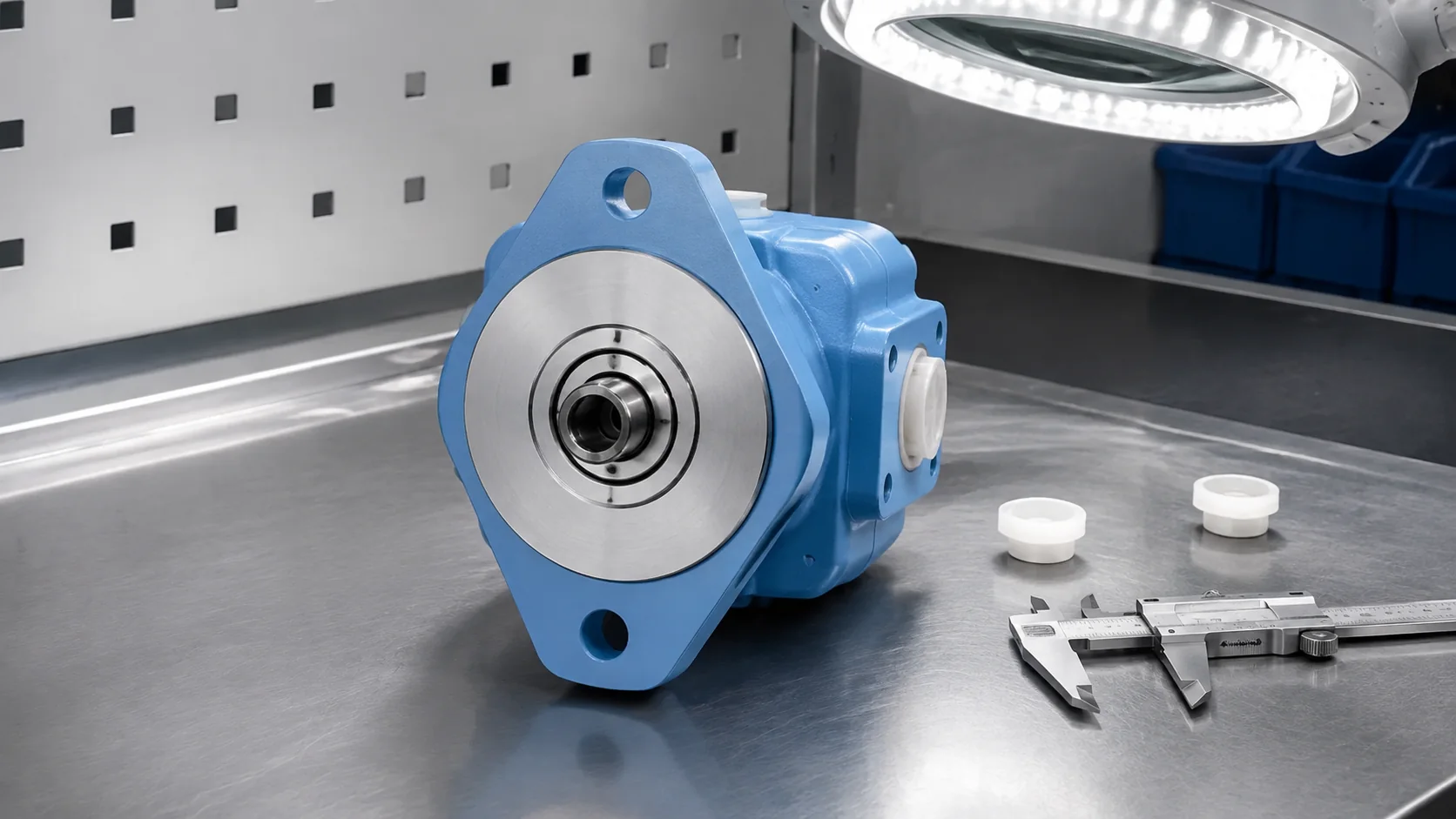
Many balanced vane pumps use replaceable cartridges. Serviceability is an advantage only when the correct cartridge is installed cleanly and in the right orientation. Ring, rotor, vanes, and plates may have directional features. Reversing rotation can require an approved reconfiguration; simply turning parts over may be unsafe.
Before removal, mark shaft viewing direction, rotation arrow, inlet and outlet ports, drain connection, cartridge orientation, and plate sequence. Preserve the failed parts and photograph wear patterns. Vane-tip polishing, ring scoring, plate wash, broken vanes, and darkened oil are evidence, not complete diagnoses. Investigate contamination, lubrication, inlet condition, pressure transients, and wrong assembly.
Application and selection guidance
Balanced fixed-displacement vane pumps commonly fit machine tools, industrial power units, presses, plastics machinery, and circuits valuing smooth delivery. Variable unbalanced vane designs can fit systems needing adjustable flow or pressure-compensated behavior. Application labels remain secondary to the actual duty cycle and specifications.
When replacing a pump, separate hydraulic compatibility from mechanical fit. Two units may share a nominal displacement yet use different port timing, shaft torque capacity, side-load tolerance, compensator behavior, minimum speed, drain arrangement, or cold-start requirement. Confirm the drive can supply torque at maximum required pressure and that the relief or compensator setting stays within every connected component’s rating. Also review how the machine unloads at neutral: a fixed pump circulating across a relief valve wastes energy and heats oil, while a variable pump needs the correct control signal and sensing path to reduce displacement. Record normal cycle times, dwell periods, simultaneous actuator demand, and start frequency. These observations are more useful than describing the machine only as a press, loader, or power unit.
Prance Hydraulic’s vane pump family sits within the wider hydraulic pump overview. Use the related guides on hydraulic vane pump types, vane pump applications, and hydraulic fluid viscosity as complementary checks.
RFQ checklist
- Balanced, unbalanced, fixed, or variable architecture
- Displacement range and required flow at operating speed
- Continuous and peak pressure with duty durations
- Rotation defined from the shaft end
- Shaft, flange, pilot, ports, and cartridge designation
- Control type and required external signals
- Fluid, viscosity, temperature, cleanliness, and inlet limits
- Noise target and measurement condition
- Drive alignment, coupling, and mounting orientation
- Existing code, photographs, circuit, and failure evidence
Educational video: how vane pumps work

Open the vane pump animation on YouTube. Confirm product-specific limits separately.
FAQ
What makes a vane pump hydraulically balanced?
Two opposed outlet pressure zones act around the rotor so their major radial forces largely cancel.
Is every variable vane pump unbalanced?
Many variable designs use an eccentric circular ring and are hydraulically unbalanced, but identify the exact architecture from its technical documentation.
Does balanced mean the pump has no bearing load?
No. It reduces the main hydraulic radial resultant; bearings still carry mechanical, residual, transient, and drive loads.
Can a balanced vane cartridge be installed in either direction?
No assumption is safe. Cartridge and plate features can be directional. Follow the approved rotation and assembly procedure.
Why does a vane pump lose flow when hot?
Lower hot viscosity and wear can increase internal leakage. Confirm oil condition, clearances, pressure, speed, and temperature before deciding the cause.