Wenzhou Prance Hydraulic Equipment Co., Ltd

Bearingless Hydraulic Motors: External Bearing and Shaft Support Requirements
A bearingless hydraulic motor transfers the responsibility for supporting the driven shaft to the surrounding machine or gearbox. A standard motor normally includes an output-shaft bearing arrangement, although its allowable loads still depend on the exact model. Choose the bearingless arrangement only when the mating equipment has been designed to carry the required radial and axial forces and to maintain the specified coupling geometry. Equal displacement and similar mounting dimensions do not make the two arrangements interchangeable.
This comparison addresses hydraulic motor integration. It does not concern magnetic-bearing electric motors. Terms such as short, ultrashort, and bearingless vary between manufacturers; the assembly drawing defines what is actually included.
Identify what the motor supplies and what the machine must supply
A hydraulic motor converts pressure and flow into torque and rotation. Supporting a wheel, pulley, pinion, or gearbox input introduces a separate mechanical task: locating the rotating parts and carrying their external forces. In a standard shaft-output motor, bearings inside the motor provide some of that support within documented limits.
A bearingless or shortened motor arrangement can instead connect its torque-generating section directly to a supported shaft in the mating equipment. Depending on the design, an output shaft may be absent, shortened, or replaced by a coupling interface. Do not infer the exact arrangement from a product-family name. Ask for the section drawing, interface drawing, and installation requirements for the complete ordered code.
The bearing support has not become unnecessary. It has moved elsewhere in the assembly. A compact motor can therefore create additional obligations for the gearbox housing, bearing arrangement, coupling, seals, and assembly process. Evaluate the complete drive rather than comparing the motor’s envelope or purchase price alone.
Trace the load path before comparing torque ratings
Start at the driven element. A sprocket subjects its shaft to chain forces, a helical gear introduces axial force as well as radial force, and a wheel produces loads that vary with vehicle weight and terrain. Trace those forces through the shaft and bearings into the housing and mounting structure.
Then trace torque separately from the hydraulic motor to the load. The component that transmits torque is not automatically suitable for locating the shaft or reacting thrust. A spline designed to transmit rotation can be damaged if an unintended axial force presses it against a stop. Similarly, a coupling that permits limited misalignment does not remove the need for adequately supported shafts.
For an illustrative static check, a transverse load of 1000 N acting 0.10 m from a reference plane creates a bending moment of 100 N·m about that plane. This is an assumed example, not a motor rating or a bearing-life calculation. The actual bearing reactions depend on support spacing, load direction, and the positions of all applied forces. Dynamic and shock loads require additional analysis.
Compare the complete installation
The following table describes integration responsibilities. It contains no numerical load ratings. Obtain those from the selected motor, bearing, coupling, and gearbox documentation. General hydraulic conversion principles are covered in the NPTEL source, while bearing damage and cause analysis are addressed in the SKF reference below.
| Decision | Standard shaft-output arrangement | Bearingless or integrated arrangement |
|---|---|---|
| Shaft support | Check the motor’s documented bearing capacity and load location | Verify the mating machine’s bearing arrangement and housing stiffness |
| Output connection | Confirm shaft, key or spline, engagement, and coupling limits | Confirm the exact mating interface, engagement, and axial location |
| Radial load | Compare direction and overhang with the model’s limits | Calculate reactions in the external support system |
| Axial load | Check permitted thrust and direction | Provide a defined thrust path through the mating bearings |
| Lubrication and sealing | Follow motor and coupling instructions | Establish which fluid lubricates each interface and how fluids remain separated |
| Service replacement | Verify complete code and installed accessories | Verify the motor and counterpart as a matched assembly |
A standard motor is not an unlimited shaft support
A conventional motor may simplify installation, but its bearing capacity still has boundaries. A pulley placed farther from the mounting flange can increase bearing demand even when the belt force is unchanged. The same nominal force applied at a different position can therefore require a different motor or an external bearing support.
Use the manufacturer’s load diagram with its stated reference distance and direction. Check whether the graph applies at the intended pressure, speed, duty, and life criterion. A peak hydraulic torque limit and a radial-load capacity are different constraints. Passing one does not establish compliance with the other.
Do not select a standard motor merely because its shaft diameter matches the hub. Establish the fit, retention method, allowable overhang, load spectrum, and start-stop behavior. If the driven equipment already contains a supported input shaft, an appropriate coupling may keep external forces out of the motor, but the coupling and alignment still require verification.
External bearings must maintain the interface geometry
For a bearingless arrangement, support stiffness can matter as much as nominal bearing capacity. Housing deflection or shaft movement under load can disturb coupling alignment, sealing surfaces, or the relative position of rotating parts. A bearing-life calculation using forces alone does not demonstrate that the interface remains within installation tolerances.
Ask the assembly designer to define radial location, axial location, and any intended float. Avoid creating two incompatible axial locating systems that trap the shaft as temperature changes. Conversely, do not leave the shaft free to move far enough to reduce spline engagement or contact adjacent components. The permitted movement comes from the particular design, not a generic bearingless-motor rule.
Assembly tolerances accumulate across pilot diameters, bearing seats, housing faces, and coupling dimensions. Inspect these features before drawing the motor into place with mounting bolts. Resistance during assembly can indicate interference or incorrect engagement; using bolt force to close an unexplained gap can damage the interface without making the geometry correct.
Lubrication and sealing are part of the selection
Identify whether the coupling is lubricated by hydraulic fluid, gearbox lubricant, or an independently specified lubricant. Establish the fluid boundary between the motor and the mating equipment. An interface that appears mechanically compatible may use different sealing, drain, or lubrication provisions.
Check case-pressure and drain requirements for the exact motor configuration. Return pressure, local restrictions, and the location of a drain connection can influence seal conditions. Do not assume that a bearingless version uses the same drain arrangement as a standard version with a different front housing.
Contamination control also becomes an assembly issue. An open mating interface can admit particles during installation, and incorrect cleaning or sealant use can introduce debris directly into the drive. Keep components protected until assembly, use the specified cleaning method, and avoid treating grease or thread compound as a universal remedy for a coupling that does not fit.
Relate the comparison to the actual catalog product
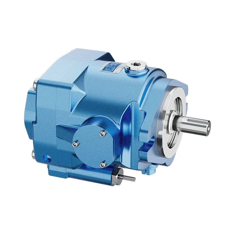
Prance’s BMS gerotor orbit motor page provides an actual shaft-output product reference for this comparison. The original website photographs show the external housing, mounting flange, and shaft. They should not be read as photographs of a bearingless variant, an internal bearing arrangement, or an approved gearbox integration.
For a BMS enquiry, request the full model documentation and the allowable output loads at the intended position. If an integrated motor is required, describe the counterpart rather than asking only for an equivalent displacement. The supplier needs to know which part supports the shaft and which part transmits torque.
The distinction also matters when replacing a failed assembly. Replacing the motor alone will not correct an external bearing seat that has become loose or a housing that deflects under load. Preserve the original failure evidence and inspect the supported shaft, coupling contact pattern, seals, and mounting condition before assigning the cause to the hydraulic section.

Commission the motor and counterpart as one drive
Plan a controlled commissioning sequence based on the machine manufacturer’s instructions. Before operation, verify fasteners, shaft retention, coupling engagement, alignment, lubricant, drain routing, and guards. Support loads and isolate stored energy before inspection; do not use hand contact near a rotating coupling to judge smoothness.
Begin with the approved low-demand condition and check for abnormal noise, leakage, temperature rise, or movement. Introduce load only through the prescribed procedure. Measurements should include hydraulic pressure and flow, rotational behavior, and the condition of the mechanical support. A satisfactory no-load run cannot establish bearing capacity under the real external load.
Acceptance should cover the intended duty cycle, direction changes, starting conditions, and thermal condition. Keep the motor’s hydraulic limits separate from the gearbox and bearing limits in the final record. If any interface requirement remains unknown, resolve it before releasing the drive for service rather than using a brief successful run as proof of compatibility.

Frequently asked questions
Does bearingless mean there are no bearings anywhere in the drive?
No. The driven assembly still needs a defined support arrangement. The term usually describes which support components are omitted from the motor package. Confirm the exact included parts and required counterpart using the ordered-code drawing.
Can a bearingless motor replace a standard motor with the same displacement?
Not on that basis alone. Displacement concerns hydraulic volume per revolution. Replacement also requires compatible shaft support, coupling, mounting, sealing, drain provisions, and operating limits. The complete mechanical assembly must be reviewed.
Is a short motor always bearingless?
No universal naming rule can establish that. Manufacturers offer different short and ultrashort constructions. Some retain features that others omit. Use the section and installation drawings rather than translating a family name into an assumed internal design.
Can an external bearing make a standard motor suitable for any pulley load?
No. The bearing arrangement and coupling must actually redirect the forces as intended, and the complete assembly must remain aligned. Check residual loads at the motor shaft, the support structure, and the load spectrum before accepting the arrangement.
What information makes an integrated-motor enquiry useful?
Provide the mating drawing, bearing arrangement, shaft and spline details, load directions and positions, torque-speed duty, pressure and flow range, lubricant boundaries, and permitted axial movement. Identify unverified assumptions so they can be resolved before manufacture or assembly.
Related product and engineering resources
Hydraulic Gerotor Orbit Motor BMS, hydraulic motor product range, Hydraulic Motor Shaft Load: Radial, Axial, and Overhung Limits, Hydraulic Motor Cold Starts: Viscosity, Breakaway Torque, and Back Pressure. Confirm the complete product code and application requirements when requesting a configuration review.
Technical references
- SKF: bearing damage mechanisms and cause analysis
- NPTEL: hydraulic torque, shaft power and system calculations
Further learning: hydraulic motors
6.3 – Hydraulic Motors by NPTEL-NOC IITM provides background on motor operating principles. The motor fundamentals explain torque generation; shaft support and counterpart integration remain separate mechanical design responsibilities. It supplements the component fundamentals; it is not a test procedure for the complete circuit discussed above.