Wenzhou Prance Hydraulic Equipment Co., Ltd

Hydraulic Fan Motor Selection: Speed, Inertia, and Coast-Down
Select a hydraulic fan motor by matching the fan’s required speed, torque, acceleration, and coast-down behavior with the verified capability of the motor and circuit. Do not choose from displacement or nominal power alone. A cooling fan is a rotating aerodynamic load: its steady demand changes strongly with speed, while startup and shutdown also involve stored rotational energy. The circuit must supply the useful operating range and manage the fan when the supply changes or stops.
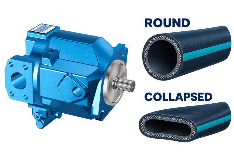
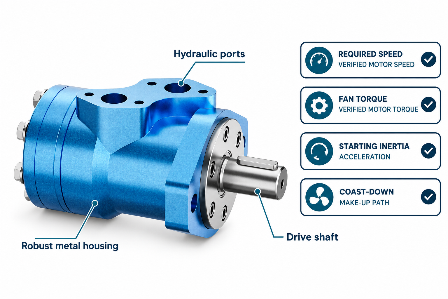
The BMP catalog motor shown in the illustrations is an exterior product reference. The photograph does not establish that a particular displacement or speed range is suitable for your fan, or that the motor contains a built-in make-up or braking arrangement. Suitability requires the exact motor documentation and the actual fan duty.
Begin with the fan and cooling system
Obtain the fan’s performance information for its diameter, blade arrangement, airflow resistance, and relevant air conditions. The cooling package determines the operating point; a motor cannot be selected reliably from a fan’s free-air speed description alone. Include restrictions through heat exchangers, guards, ducts, and other parts that affect the air path.
State the cooling demand across ambient and machine operating conditions. The maximum useful fan speed, the controlled lower range, starting conditions, and any permitted reversing operation should be explicit. Distinguish continuous operation from short events. If the fan supplier has limits for speed, acceleration, mounting, or imbalance, preserve those limits in the drive specification rather than assuming a larger hydraulic motor makes every operating condition acceptable.
Use fan laws with their conditions attached
For the same fan geometry under appropriate similarity conditions, familiar fan-law relationships describe airflow approximately in proportion to speed, torque approximately in proportion to speed squared, and shaft power approximately in proportion to speed cubed. Air density and the system operating point matter; these relationships are not a substitute for the actual fan curve or every transient condition.
As a normalized illustration, reducing speed from 1.00 to 0.80 gives a torque ratio of 0.80² = 0.64 and a power ratio of 0.80³ = 0.512 under those assumptions. These are mathematical ratios, not BMP performance ratings or a promise of identical installed electrical or fuel savings. Pump, valve, mechanical, and other system losses must be considered when estimating the complete machine’s energy use.
Convert fan demand into a motor operating range
For a motor of displacement D in cubic centimeters per revolution, the ideal relationship between flow Q in liters per minute and speed n in revolutions per minute is n = 1000 × Q / D. Actual operation includes volumetric losses and depends on the installed conditions. Use the relevant motor data rather than treating the ideal expression as a guaranteed output.
The ideal torque relationship using pressure difference Δp in bar is T = Δp × D / (20π) in newton-meters. Actual delivered torque also depends on mechanical and hydraulic losses. The pressure difference is across the motor; an upstream gauge reading alone does not necessarily provide it when return pressure and circuit losses are present. Confirm continuous speed, torque, pressure, and any intermittent limits for the exact configuration.
Check startup separately from steady fan demand
At startup the drive must accelerate the fan and associated rotating parts as well as overcome the resisting load. In a simplified rotational model, acceleration torque includes J × α, where J is rotational inertia and α is angular acceleration. A short requested acceleration time can therefore require a different torque condition from the eventual steady fan duty.
Obtain the relevant inertia and starting requirements from the fan and drivetrain information. Do not infer them from appearance. Review the motor’s starting capability and the circuit’s controlled pressure and flow behavior. Avoid treating a high theoretical stall-torque figure as the whole startup assessment. The motor, fan, coupling, shaft support, and hydraulic controls all need to remain within their applicable limits during the transition.
Compare requirements with verified capability
| Fan-drive requirement | Information needed | Motor and circuit check |
|---|---|---|
| Highest continuous cooling demand | Fan curve and actual air-system resistance | Continuous speed, torque, flow, and pressure-difference capability |
| Controlled lower-speed operation | Required stable range and control method | Motor low-speed behavior and available flow control |
| Startup | Rotating inertia and intended acceleration | Starting torque, pressure control, and mechanical limits |
| Shutdown | Stored rotational energy and required stop behavior | Coast-down, displaced-fluid path, and pressure conditions |
| Mechanical interface | Shaft, coupling, support, and fan loads | Permitted external loads, mounting, and alignment |
| Temperature range | Fluid and ambient conditions across the cycle | Fluid compatibility, operating limits, and cooling losses |
The table organizes application review. It does not turn a catalog series name into approval for a particular cooling package.
Decide how speed will be controlled
The control method may change pump delivery, motor displacement where applicable, or the flow through a suitable control arrangement. Each approach has its own operating range, response, and loss implications. Define the actual architecture instead of assuming that closing a valve is always an efficient way to reduce fan speed.
When flow is throttled, pressure loss can generate heat in addition to the power needed at the fan shaft. When pump delivery is varied, review the pump and prime mover together with the motor. Match the control range to cooling needs and verify behavior at the minimum useful fan speed. Do not claim an energy saving from the fan cube relationship without evaluating where hydraulic power is still being dissipated elsewhere in the installed system.
Plan for coast-down when supply falls
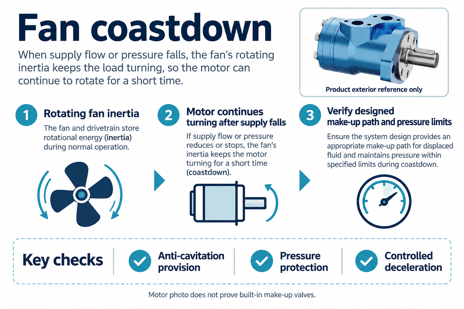
A rotating fan retains energy after commanded flow or pressure is reduced. During coast-down it can continue driving the connected motor mechanically. The circuit must accommodate the resulting fluid movement and pressure conditions. Simply removing commanded supply is not proof that the motor immediately stops or that all its ports remain in a suitable condition.
Review the approved make-up path, pressure protection, return conditions, and any controlled deceleration requirement with the actual motor and circuit. A catalog photograph does not prove the presence of internal anti-cavitation valves. Do not add an improvised bypass based only on a generic sketch. The arrangement must match both directions of possible operation, the selected motor’s limits, and the machine’s intended shutdown behavior.
Include return and case-pressure requirements
Return pressure affects the pressure difference available to produce torque. Where a separate case drain is required or an allowable case-pressure condition applies, it must be assessed independently using the exact motor documentation. Connecting a required drain to an unsuitable return location can create a different problem even when the fan reaches its desired speed.
Assess fluid paths during steady operation, startup, and coast-down rather than reviewing only one commanded state. Include fittings, coolers, filters, and other components that affect the relevant pressures. Keep all stated limits tied to the actual configuration and test conditions. This article deliberately does not prescribe one universal case-pressure or return-pressure value for all fan motors.
Treat the shaft connection as a load path
A motor that has enough hydraulic torque may still be unsuitable for the mechanical installation. Determine how fan weight, aerodynamic forces, imbalance, belt or coupling forces, and other loads reach the shaft and mounting. The actual arrangement matters; a directly mounted fan can present a different problem from a separately supported fan driven through a coupling.
Use the selected motor’s permitted shaft-load information and the fan supplier’s mounting requirements. Do not make the hydraulic connections carry mechanical loads or use an assumed shaft diameter as a bearing-capacity rating. Confirm alignment, retention, guarding, and maintenance access. If the duty requires another support arrangement or transmission, include that design work before treating the motor selection as complete.
Verify the cooling result and the hydraulic result
Commission under the machine’s approved isolation, guarding, and startup procedures. A fan can remain hazardous while coasting after power is removed. Control access to rotating parts and address hydraulic or mechanical stored energy before service work.
A useful verification records fan speed, cooling performance under the relevant conditions, motor pressure difference and flow where required, temperatures, leakage, and transition behavior. Check the operating range that matters to the machine rather than demonstrating only maximum unloaded speed. Include startup and shutdown observations selected during the design review. Retain any limitations of the test, especially if full ambient or load conditions could not be reproduced, so a partial demonstration is not mistaken for proof of every duty point.
Frequently asked questions
Can fan power be estimated from the speed cube relationship?
It can support an estimate for the same fan under appropriate similarity conditions. Use the actual fan curve and include hydraulic and mechanical losses when evaluating installed power. The normalized relationship is not a particular motor’s efficiency map.
Is the smallest displacement that reaches the speed always best?
No. Torque, continuous speed, pressure difference, starting behavior, control range, and mechanical loads must also match. A speed calculation alone cannot establish motor suitability or the complete drive’s energy performance.
Does switching off flow stop the fan immediately?
No. Rotational inertia can keep the fan and motor turning. The approved circuit must manage displaced fluid, pressure conditions, make-up needs, and the required stopping behavior during that transition.
Can a BMP photograph confirm a suitable fan motor?
No. It identifies an exterior product reference, not the required operating envelope or optional circuit features. Confirm the exact displacement, configuration, documented limits, and fan duty with the responsible supplier or engineer.
What should be included in a fan-drive enquiry?
Provide the fan curve, speed range, inertia, air-system conditions, acceleration and stop requirements, available hydraulic supply, fluid and temperature range, mechanical arrangement, and the expected control method. These inputs allow a meaningful review rather than a selection from nominal power alone.
Product and related engineering resources
The Hydraulic Low Speed High Torque Orbit Motor BMP catalog exterior is used as the real product reference in these explanatory images. It does not establish the approved service method, optional construction, or operating limits for an individual order. Confirm the complete code and its documentation. Related resources: Hydraulic Low Speed High Torque Orbit Motor BMP, hydraulic motor range, Hydraulic Motor Speed Calculation From Flow and Displacement, Hydraulic Motor Power Calculation: Torque, Speed, and Efficiency, Hydraulic Motor Anti-Cavitation Valve: When Make-Up Flow Is Needed.
Sources and limits of this guide
The university resource supports the component operating principles. NIOSH supplies hazardous-energy prevention context; exact machine isolation and component service requirements still need their approved procedures. Sources explain general operating principles, not performance ratings or optional features of the pictured catalog component.
- NPTEL: Fundamentals of Industrial Oil Hydraulics and Pneumatics
- NIOSH: preventing injuries from hazardous energy
- U.S. Department of Energy: Improving Fan System Performance
University lesson: operating principles
NPTEL-NOC IITM presents 6.3 – Hydraulic Motors. The lesson supports the motor operating principles used in the engineering discussion; it is not a model-specific repair, storage, or installation approval.