Wenzhou Prance Hydraulic Equipment Co., Ltd

Hydraulic Pump Case-Pressure Spikes at Startup: What to Measure
A hydraulic pump case-pressure startup spike is a short housing-pressure event that can disappear before an ordinary gauge settles. Diagnose it by measuring at the approved case point with a suitable transient-capable instrument, then comparing the event with drain-destination pressure, oil temperature and shaft speed on the same timeline. Do not confuse it with the main working-pressure spike. The aim is to distinguish a real case-pressure excursion from drain-path restriction, another component’s return pulse or a measurement artifact before changing the pump or its drain arrangement.
Define the startup event you actually need to capture
Startup can mean the first shaft rotation after an overnight stop, acceleration from idle, engagement of a driven section or the first command that moves the swashplate. Those events may occur at different times. A pressure peak associated with one of them should not be attributed automatically to the others.
Start with the complaint and the existing machine sequence. Does leakage appear only on the first cold start? Does the pressure trace rise before a displacement command? Was a shared return connection changed during recent service? Record the sequence before altering settings or routing. A warm restart is a useful comparison only when the remaining operating conditions are known.
Treat external leakage or a damaged seal as a reason for controlled service, not an invitation to reproduce the fault repeatedly. Establish the manufacturer’s test arrangement and stop criteria before starting. Install instruments only after isolation, pressure release and load support. The NIOSH hazardous-energy source linked below explains why shutdown alone does not control every energy source.
Distinguish three pressures that are often called case pressure
Pressure at a housing test port describes a local case condition. Pressure farther down the drain line includes the effect of its location and downstream network. Pressure at the reservoir or other drain destination establishes the reference against which the path is discharging. These readings can differ during a short transient.
For illustration, suppose a hypothetical instrument at the approved case point records 3.0 bar gauge while the drain destination simultaneously records 1.0 bar gauge. The difference is 2.0 bar at that instant. If both rise by nearly the same amount, the destination network deserves attention; if their difference grows substantially, the connecting path deserves attention. This is a diagnostic interpretation, not an allowable limit or an AA4VG rating.
The exact port and pressure reference matter. A charge port or main-loop port is not a convenient substitute for a case connection. Nor does the difference between two widely separated measurements automatically represent friction loss alone: elevation, local flow acceleration and the chosen boundaries can contribute. Keep the physical layout beside the traces.
Select an instrument that can answer a transient question
A readable dial gauge can establish a steady condition yet miss a brief peak. A logger can also miss it if its acquisition rate, filtering or sensor response is unsuitable. Distinguish the sensor’s response from the display refresh and the rate at which data are actually saved.
Choose the pressure range from the expected case conditions and credible abnormal event, while protecting the instrument against possible overpressure. A main-system-range sensor may provide poor resolution for a small case-pressure change. An extremely narrow-range sensor may be damaged if connected to the wrong port. Approved connections and an appropriate protection arrangement are necessary for both accuracy and safety.
For a hypothetical 0.10-second feature, a logger saving one value each second cannot describe the event reliably. Saving at 100 samples per second would provide about ten samples across that interval, but it still does not prove adequate accuracy or bandwidth. The real waveform, anti-alias filtering and complete measurement chain determine the required acquisition settings. Ask the instrumentation specialist to specify them for the event.
Avoid turning the pressure measurement into a flow restriction
Temporary equipment can change the condition it is intended to observe. An added adapter with a small passage, an inline flowmeter or a long temporary hose can increase resistance. A pressure branch can also distort the measured waveform through its length, trapped air or damping.
Use the manufacturer’s approved sensing location and the least intrusive suitable arrangement. Document every added fitting and instrument. Do not route the case flow through a convenient meter unless that meter’s installation and pressure loss are acceptable for the exact application. The normal drain path must remain functional throughout the test.
Never cap the case drain to make a pressure reading, and never open a line while the machine is operating. A suspected transient does not justify bypassing normal pressure-control precautions. If the necessary sensing arrangement cannot be installed safely, move the work to a qualified service environment rather than collecting an ambiguous reading.
Compare the first cold start with a controlled warm condition
Oil viscosity affects resistance through lines and components, so a cold-only peak can point toward the drain path. It does not prove that changing oil grade is the correct repair. Check the specified fluid, actual temperature, routing and installed components first.
During a comparable test, relate case pressure to shaft acceleration and displacement command. A peak that appears with another actuator’s return event may originate in a shared network. A peak coincident with the pump’s first rotation may require examination of the local housing and drain arrangement. A delayed peak after a command transition may call for a different interpretation.
Use only operating conditions permitted by the manufacturer. Do not intentionally chill oil beyond its approved range or repeatedly accelerate a leaking unit. If the recorded event approaches a documented boundary, stop. Preserving one useful trace is better than generating a repeatable failure through unnecessary starts.
Interpret paired traces before choosing a repair
The following qualitative table separates plausible directions of investigation. It does not diagnose an internal fault from a pressure shape alone.
| Recorded pattern | Question to investigate | Useful separating evidence |
|---|---|---|
| Case and drain destination rise together | Is another return source pressurizing the destination? | Synchronized destination pressure and machine event log |
| Case rises while destination stays relatively stable | Is the local drain path restrictive during acceleration? | Actual routing, fluid temperature and approved flow assessment |
| Peak is much larger only when oil is cold | Does viscosity expose excessive path resistance? | Comparable speed and command at documented temperatures |
| Peak changes after test fittings are installed | Is the measurement arrangement altering the event? | Connection drawing and independent instrument review |
| Short peak appears on only one recording channel | Is channel timing, filtering or sensor response misleading? | Calibration, timing alignment and raw unfiltered data |
| Pressure stays high after startup | Has a transient complaint become a sustained restriction? | Steady case/destination readings and exact continuous limit |
Several mechanisms can coexist. For example, a pressurized destination and a restrictive line can both contribute. Avoid replacing a pump solely because its case trace is the first signal that appears abnormal. Compare the conditions at its interfaces before deciding where the cause lies.
Use model-specific peak criteria, not the working-pressure rating
The allowable case condition is distinct from the main-loop working pressure. Some component documentation distinguishes continuous and intermittent conditions, and the definition of an intermittent event can itself matter. A short duration does not make an arbitrary peak acceptable.
The Danfoss H1T reference manual treats case pressure separately from system, charge and servo pressures. Its values and test procedures apply to the named reference pumps. They must not be used as AA4VG limits. Obtain the complete model’s controlled requirements, including pressure reference, duration and applicable seal or installation options.
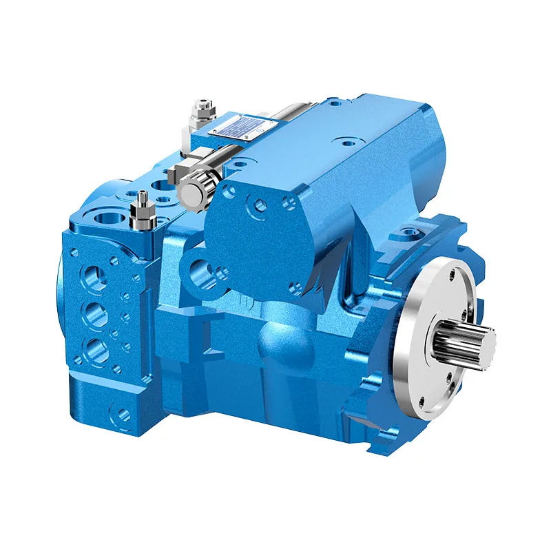
The Prance AA4VG original photographs below identify the related closed-loop pump family for a configuration review. They do not show a startup test, establish a sensor location or certify a particular seal option. Send the full product code and installation diagram with the trace. That allows a supplier to review the real assembly instead of judging from a generic housing picture.

Verify the correction using the same measurement boundary
A repair should follow the confirmed mechanism. A damaged or incorrectly routed drain connection requires a different action from a destination-network pressure pulse. A faulty measurement setup requires correction of the test rather than alteration of the machine. Preserve the original evidence before making the authorized change.
Afterward, compare the same sensing points, acquisition settings and operating sequence. Include the conditions that exposed the complaint, within the approved test range. A lower peak obtained only because shaft acceleration was reduced or the oil was warmer is not an equivalent confirmation.
Keep the raw traces, instrument specifications, pressure references and final acceptance criteria with the service record. If a replacement is required, include the drain interface and destination conditions in its specification review. This makes the startup-pressure issue part of the installation decision and reduces the chance of exposing the replacement to the same unresolved condition.

Frequently asked questions
Can a normal dial gauge prove there was no startup spike?
No. It may establish steady pressure but miss a short event. The sensor, connection, acquisition rate and filtering must be suitable for the transient. A smooth display is not sufficient evidence that a brief peak did not occur.
Is the main-loop pressure limit also the case-pressure limit?
No. They apply to different parts of the unit and different loading conditions. Use the exact pump’s case-pressure requirements, including its stated reference and duration, rather than applying the main working-pressure rating to the housing.
Does a cold-only peak mean the pump is worn out?
Not necessarily. Cold viscosity can increase drain-path resistance, and shared return pressure or instrumentation can contribute. Compare synchronized pressure and temperature evidence before drawing an internal-wear conclusion or ordering a replacement.
Should a flowmeter be inserted into the drain for every test?
No. Added restriction can change case pressure. Measure flow only where the selected meter and connection are approved for the application. A pressure-focused diagnostic may require a separate flow assessment rather than an intrusive temporary installation.
What makes a useful startup-pressure report?
Include the complete model code, schematic, sensing locations, pressure references, fluid temperature, shaft-speed and command timeline, raw pressure traces and acquisition settings. State the acceptance document and whether the same event was verified after repair.
Related product and engineering resources
Closed Loop Variable Displacement Piston Pump AA4VG, hydraulic pump product range, Hydraulic Pump Case Pressure: Limits, Measurement, and Failure Risks, Hydraulic Pump Case Drain Line Sizing and Routing Guide. Confirm the complete product code and application requirements when requesting a configuration review.
Technical references
- Danfoss H1T service manual: reference control and measurement architecture, not AA4VG specifications
- NIOSH: Preventing Deaths from Uncontrolled Hazardous Energy
Further learning: hydraulic pumps
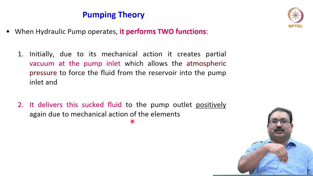
3.2 – Hydraulic Pumps by NPTEL-NOC IITM provides background on pump operating principles. Pump fundamentals explain displacement and flow. This lecture does not demonstrate the diagnostic or recovery procedure described here. It supplements the component fundamentals; it is not a test procedure for the complete circuit discussed above.