Wenzhou Prance Hydraulic Equipment Co., Ltd

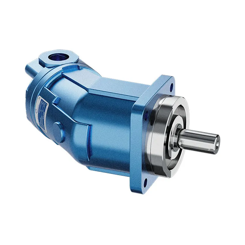
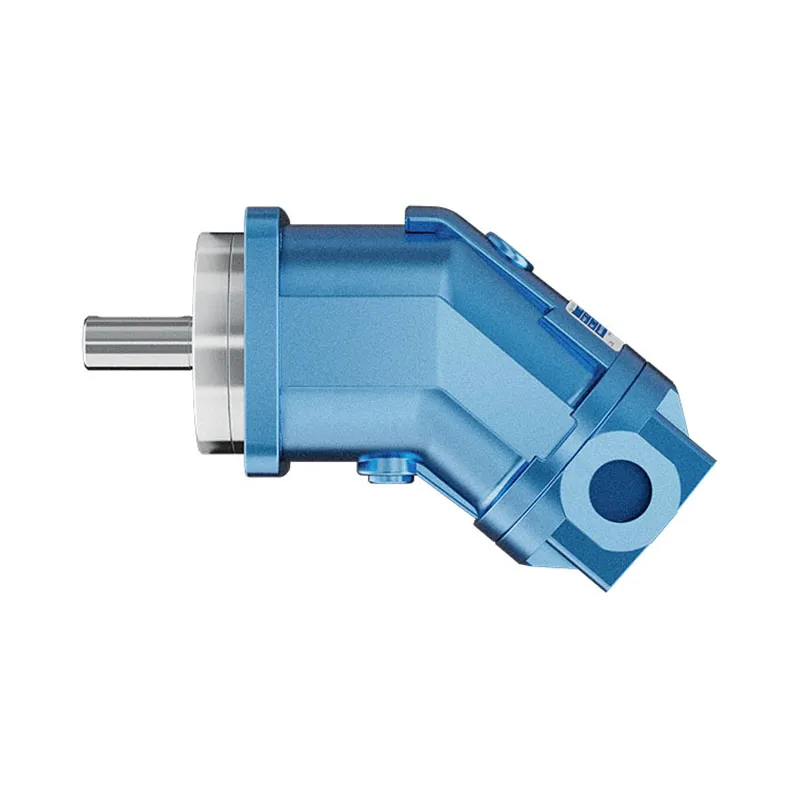
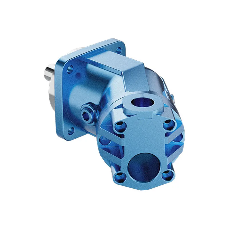
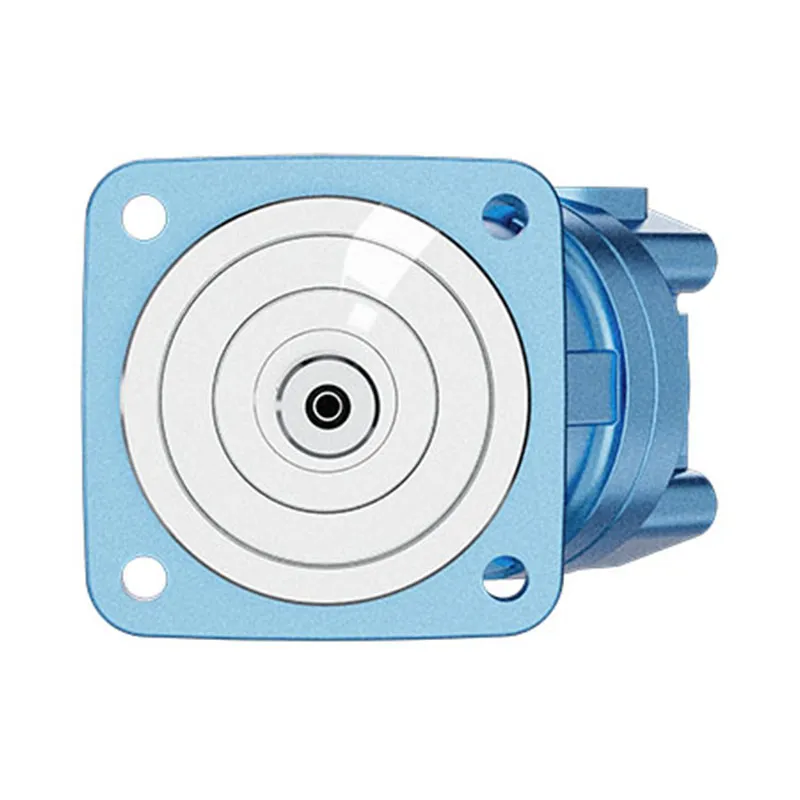
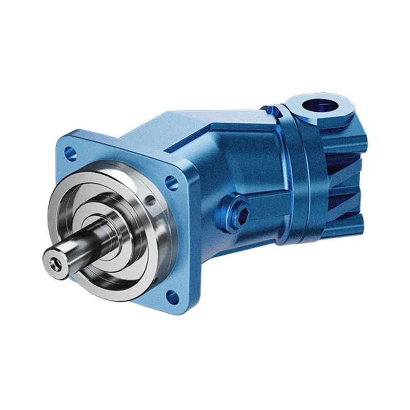

A2FO Series Axial Piston Fixed Displacement Pump
1.Fixed displacement pump A2FO of axial piston , bent axis design.suitable for hydrostatic drives in open circuits.
2.Use in mobile and industrial applications
3.output flow is proportional to drive speed and displacement
4.They drive shaft bearings are designed to give the service life expected in these areas of operation
5.High power density
Detailed description
The A2FO is a fixed displacement pump featuring an axial piston, bent axis design, specifically engineered for hydrostatic drives in open-circuit systems. Its bent axis structure ensures efficient power transmission and stable oil flow output, which is critical for the reliable operation of open-circuit hydrostatic drive systems in various scenarios. This pump is widely applicable to both mobile and industrial applications, including construction machinery, agricultural equipment, industrial hydraulic stations, and other equipment that requires stable hydraulic power supply, adapting well to different working environments and load conditions. The output flow of the A2FO pump is strictly proportional to the drive speed and displacement, meaning the flow can be predictably adjusted by changing the drive speed, ensuring consistent performance that matches the actual working demands of the system. Its drive shaft bearings are specially designed and optimized to meet the service life requirements of mobile and industrial operation areas, with strong wear resistance and load-bearing capacity to reduce maintenance frequency. Additionally, the pump boasts high power density, integrating powerful hydraulic output into a compact structure, which saves installation space while delivering reliable and efficient power, making it an ideal choice for equipment with limited installation space and high power requirements.
Selection and RFQ
This product series should be selected against the approved hydraulic circuit. Confirm required flow or displacement, continuous and peak pressure, drive speed, control arrangement, fluid and installation interface before final selection.
Information to include in your RFQ
- Required displacement or flow at operating speed
- Continuous and peak system pressure
- Drive speed, control requirement and circuit type
- Mounting flange, shaft, ports, fluid and filtration requirement
Related resources
Model Code
| A2F | ○ | 80 | /6 | 1 | R | -P | A | B | 0.5 |
| Axial piston unit | Mode of operation | Size(ml/r) | Series | Index | Direction of rotation | Seals | Shaft end | Mounting flange | Service line ports |
| A2F:
Bent axis design, fixed dispia- cement |
○:
Pump, open circuits |
10
12 16 |
6 | 1 | (Viewed on shaft end) | P:
NBR(nitrl~ caoutchouc) |
See below | B:
4-hole ISO 3019-2 |
See below |
| 23
28 32 |
|||||||||
| 45 | R:
Clockwise |
||||||||
| 56
63 |
V:
FKM(fluor~ caoutchouc) |
||||||||
| 80
90 |
L:
Counter- clockwise |
||||||||
| 107
125 |
|||||||||
| 160
180 |
Shaft end
| Size | 10 | 12 | 16 | 23 | 28 | 32 | 45 | 56 | 63 | 80 | 90 | 107 | 125 | 160 | 180 | |
| Spined shaft DIN 5480 | A | ✓ | ✓ | ✓ | ✓ | ✓ | ✓ | / | ✓ | ✓ | ✓ | ✓ | ✓ | ✓ | ✓ | ✓ |
| Z | ✓ | ✓ | / | ✓ | ✓ | / | ✓ | ✓ | / | ✓ | / | ✓ | / | ✓ | / | |
| Paralled keyed shaft,DIN 6885 | B | ✓ | ✓ | ✓ | ✓ | ✓ | ✓ | / | ✓ | ✓ | ✓ | ✓ | ✓ | ✓ | ✓ | ✓ |
| P | ✓ | ✓ | / | ✓ | ✓ | / | ✓ | ✓ | / | ✓ | / | ✓ | / | ✓ | / | |
Service line port1)
| Size | 10 | 12 | 16 | 23 | 28 | 32 | 45 | 56 | 63 | 80 | 90 | 107 | 125 | 160 | 180 |
| 05:SAE flange ports A and B,
at side and SAE flange port S,rear |
/ | / | / | ✓ | ✓ | ✓ | ✓ | ✓ | ✓ | ✓ | ✓ | ✓ | ✓ | ✓ | ✓ |
| 06:Threaded ports A and B,
at side and SAE flange port S,rear |
✓ | ✓ | ✓ | / | / | / | / | / | / | / | / | / | / | / | / |
✓=available /=not available
1)=fastening threads resp. threaded ports are metric
Technical Data
Table of values(the oretical values,ignoring ηmin and ηv; values rounded)
| Size | 10 | 12 | 16 | 23 | 28 | 32 | 45 | |||
| Displacement | Vg | mL/r | 10.3 | 12 | 16 | 22.9 | 28.1 | 32 | 45.6 | |
| Speed max | Nmax1) | rpm | 3150 | 3150 | 3150 | 2500 | 2500 | 2500 | 2240 | |
| nmax limit2) | rpm | 6000 | 6000 | 6000 | 4750 | 4750 | 4750 | 4250 | ||
| Flow max. | at nmax | qv max | L/min | 32.4 | 37.8 | 50 | 57 | 70 | 80 | 102 |
| Power at | ΔP=35MPa | Pmax | Nm/MPa | 18.9 | 22 | 29.2 | 33 | 41 | 47 | 59.5 |
| ΔP=40MPa | Pmax | Nm | 21.6 | 25 | 34 | 38 | 47 | 53 | 68 | |
| Torque at | ΔP=35MPa | T | Nm | 57 | 67 | 88 | 126 | 156 | 178 | 254 |
| ΔP=40MPa | T | Nm | 65 | 76 | 101 | 145 | 178 | 203 | 290 | |
| Filling capacity | L | 0.17 | 0.17 | 0.17 | 0.20 | 0.20 | 0.20 | 0.33 | ||
| Mass(approx.) | m | kg | 6 | 6 | 6 | 9.5 | 9.5 | 9.5 | 13.5 | |
| Size | 56 | 63 | 80 | 90 | 107 | 125 | 160 | 180 | |||
| Displacement | Vg | mL/r | 56.1 | 63 | 80.4 | 90 | 106.7 | 125 | 160.4 | 180 | |
| Speed max | Nmax1) | rpm | 2000 | 2000 | 1800 | 1800 | 1600 | 1600 | 1450 | 1450 | |
| nmax limit2) | rpm | 3750 | 3750 | 3350 | 3350 | 3000 | 3000 | 2650 | 2650 | ||
| Flow max. | at nmax | qv max | L/min | 112 | 126 | 144 | 162 | 170 | 200 | 232 | 261 |
| Power at | ΔP=35MPa | Pmax | Nm/MPa | 65 | 73.5 | 84 | 95 | 100 | 117 | 135 | 152 |
| ΔP=40MPa | Pmax | Nm | 75 | 84 | 96 | 108 | 114 | 133 | 155 | 174 | |
| Torque at | ΔP=35MPa | T | Nm | 312 | 350 | 445 | 501 | 594 | 696 | 893 | 1003 |
| ΔP=40MPa | T | Nm | 356 | 400 | 511 | 572 | 678 | 795 | 1020 | 1145 | |
| Filling capacity | L | 0.45 | 0.45 | 0.55 | 0.55 | 0.8 | 0.8 | 1.1 | 1.1 | ||
| Mass(approx.) | m | kg | 18 | 18 | 23 | 23 | 32 | 32 | 45 | 45 | |
1)the values shown are valid for an absolute pressure(Pabs)of 0.1 MPa at suction inlet S and when operated on mineral oil (with a specific mass of 0.88kg/L)
2)by increase of the input pressure (Pabs>0.1 MPa) the rotational speeds can beincreased to the max. admissible speeds nmax limit (speed limits)(see diagram page 99)
Determining the size
| Flow | qv=(Vg ∙ n ∙ ηv) / 1000 | I/min |
| Torque | T=(Vg ∙ Δp) / 20 ∙ π ∙ ηmh | Nm |
| Power | P=(2π ∙ T ∙ n)/60000=(qv ∙ Δp)/600 ∙ ηt | kW |
Vg = Displacement per revolution in mL/r
Δp = =Differential pressure in MPa
n = Speed in rpm
ηv = Volumetric efficiency
ηmh = Mechanical-hydraulic efficiency
ηt = Overall efficiency