Wenzhou Prance Hydraulic Equipment Co., Ltd

Swash Plate Angle and Pump Displacement: Calculation and Limits
Swash plate angle determines piston stroke in an axial piston pump, and stroke determines theoretical displacement. For a simplified in-line design, displacement is proportional to the tangent of the swash plate angle, not directly to the angle itself. To calculate useful delivered flow, you also need the rotating-group geometry, shaft speed and volumetric efficiency. A visible housing photograph cannot establish these internal dimensions. This guide explains the geometry, gives a transparent example and shows which manufacturer information is needed before changing a pump setting or comparing two displacement options.
What the angle actually changes
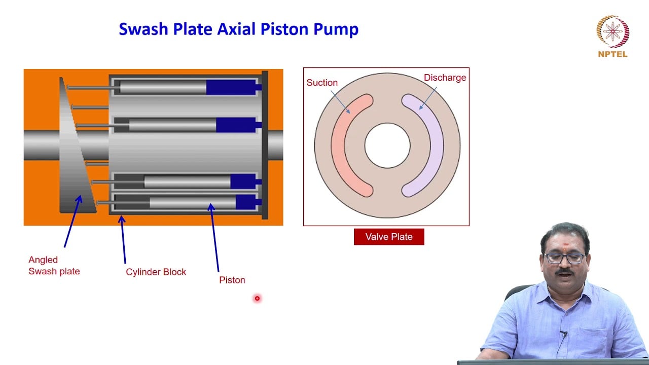
An in-line axial piston pump has pistons arranged around the drive axis. As the cylinder block rotates, the piston ends follow an inclined plate through slippers or an equivalent contact arrangement. Each piston moves through a suction stroke and a delivery stroke during a revolution. Increasing the inclination increases that travel. A larger swept volume moves through the port plate during the delivery part of the cycle, provided the inlet can fill the chambers adequately.
The angle is normally defined between the swash plate and a plane perpendicular to the shaft. Check the drawing before using a quoted angle: an angle measured from the shaft axis uses a different convention. Confusing complementary angles can produce an enormous error. The external control lever position also may not equal the internal plate angle. Linkages, control pistons, stops and compensators can change that relationship.
A pressure-compensated or load-sensing pump controls the plate automatically. Its maximum displacement adjustment, standby setting and pressure setting perform different jobs. Turning an unidentified screw to increase flow may change a pressure limit or interfere with a safe control setting. Establish the exact model, control code and approved adjustment procedure first.
A simplified displacement formula
For a conventional in-line arrangement, use Vg = z × Ap × 2R × tan(alpha), where Vg is displacement per revolution, z is the number of active pistons, Ap is the piston area, R is the radius of their pitch circle and alpha is the plate angle. Piston area is Ap = pi × d squared / 4. If d and R are measured in millimetres, the resulting volume is cubic millimetres; divide by 1,000 to obtain cubic centimetres per revolution.
This is a geometric model. It does not include port timing, compressibility, slipper leakage, cylinder-block leakage, control response or incomplete filling. Actual designs may have details that prevent direct use of the formula. Use the pump manufacturer's stated displacement as the ordering specification and use the geometry to understand sensitivity rather than reverse-engineer an unverified rating.
At an ideal zero inclination the pistons have no swept stroke. A real pump at minimum delivery may still need leakage replacement, lubrication flow or a small residual displacement. Zero on a controller display therefore does not prove zero hydraulic consumption. Conversely, an over-centre transmission pump can cross through neutral only if its design and circuit specifically permit it. An ordinary open-circuit pump must not be assumed capable of reversal.
Worked example with explicitly illustrative inputs
Assume nine pistons, each 10 mm in diameter, on a 25 mm pitch radius. These are teaching inputs, not specifications for any Prance pump. The piston area is approximately 78.54 square millimetres. At an angle of 12 degrees, stroke is 2 × 25 × tan(12 degrees), or approximately 10.63 mm. Displacement is then 9 × 78.54 × 10.63 / 1,000, approximately 7.51 cubic centimetres per revolution.
At 1,500 rpm, theoretical flow is 7.51 × 1,500 / 1,000, approximately 11.27 litres per minute. If an independently verified operating point had a volumetric efficiency of 0.90, delivered flow at that point would be approximately 10.14 litres per minute. The efficiency is an assumption for this example; it is not a typical guaranteed value and should not be transferred to a catalogue product.
Repeating the calculation at 6 degrees gives a stroke of approximately 5.26 mm and a displacement of approximately 3.71 cubic centimetres per revolution. The 6-degree displacement is slightly less than half the 12-degree result. That difference demonstrates why a linear angle-to-flow interpolation becomes inaccurate as inclination grows.
Compare settings with tangent ratios
If the piston count, diameter and pitch radius remain unchanged, the ratio of theoretical displacements is Vg2 / Vg1 = tan(alpha2) / tan(alpha1). A verified displacement at one verified angle therefore allows a geometric estimate at another angle. It does not establish whether the second angle is mechanically permitted or whether efficiency remains unchanged.
| Question | Information needed | What the result can establish |
|---|---|---|
| How does angle affect displacement? | Angle convention and rotating-group geometry | Theoretical stroke and swept volume |
| How does displacement affect flow? | Shaft speed and operating-point efficiency | Estimated delivered flow at stated conditions |
| Is a setting allowed? | Manufacturer control instructions and mechanical limits | Whether adjustment is permitted |
| Will pressure remain the same? | Circuit load and control characteristics | Expected control behaviour, not a geometry-only answer |
| Can a replacement give the same output? | Ordered displacement, control code and duty | A comparison requiring more than housing size |
Supporting technical context: NPTEL: industrial oil hydraulics, NPTEL: axial piston pump discharge geometry. Illustrative calculations and qualitative checks do not establish a product rating or universal acceptance limit.
The table is a decision guide based on axial piston geometry and hydraulic operating principles. It contains no universal pressure, speed or angle limit. Such limits come from the selected configuration's documentation.
Why measured flow can disagree with the calculation
A flow meter reports delivered flow where it is installed. A meter downstream of branches may miss lubrication, cooling or actuator-return paths. Record the test point and distinguish pump outlet flow from flow delivered to one actuator. Read speed at the same time; an engine or electric drive that slows under load changes flow even when the plate angle stays fixed.
Pressure also changes leakage. A calculation using one efficiency number across an entire pressure sweep may hide a substantial change in internal losses. Oil temperature affects viscosity, clearances and leakage behaviour. An angle test performed with cold oil cannot be compared directly with a hot operating test without recording these conditions. Verify instrument range and calibration rather than treating every disagreement as pump wear.
A compensator may reduce angle as pressure reaches its control setting. In that case, lower measured flow is an intended response. A blocked outlet is not a safe way to establish maximum displacement. Use an engineered test circuit, a suitable load device and verified protection. Personnel must follow isolation procedures before fitting instruments or opening a connection.
Use angle sensitivity when specifying a control
A controller that commands displacement needs a reliable relationship between command and actual delivery. Near a small angle, the tangent curve is approximately linear, but friction, linkage backlash and control deadband may dominate. At larger angles, the geometric curve becomes steeper. A constant change in angle does not represent a constant change in displacement over the full travel.
For a production machine, request command-to-displacement or command-to-flow data under defined pressure, speed and temperature. Specify how neutral, minimum delivery and maximum delivery are identified. If feedback is available, establish whether it measures plate position, actuator travel or actual flow. These signals describe different quantities and should not be substituted without checking the control architecture.
A control map should cover the duty that matters: approach, working stroke, hold and return, for example. A pump selected solely for maximum flow may have unsuitable behaviour at low delivery. The engineering question is whether the complete control and rotating group can supply the required operating points repeatedly, within the manufacturer's approved limits.
What to request from a pump supplier
Begin with the full model code and a drawing showing the ordered mounting, shaft, ports and control. Ask for rated geometric displacement and the conditions used for performance curves. Request the maximum and minimum displacement range for that exact control variant. If a machine depends on a particular response, ask for response data or an agreed acceptance test rather than assuming that similar catalogue families behave identically.
Provide your speed range, pressure profile, fluid specification, temperature range and duty cycle. Explain whether the application uses an open circuit or a closed transmission circuit. State whether flow is controlled by pressure compensation, load sensing, external pilot pressure or an electrical command. Include the existing protection and unloading arrangement. These details let the supplier distinguish a sizing question from a control compatibility problem.
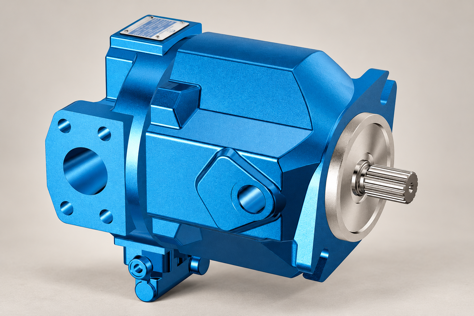
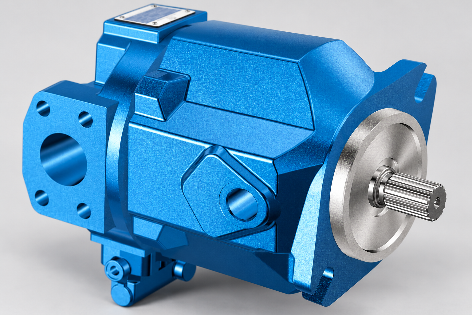
Prance lists an A10VO 31 Series variable displacement pump as a relevant product family. The illustrated exterior identifies a catalogue configuration; it does not reveal piston diameter, pitch radius or the internal angle. Confirm those facts through the ordered product documentation. Family names and visual similarity alone do not prove interchangeability with another manufacturer's component.
A practical verification sequence
First, review the circuit and manufacturer instructions without operating the machine. Identify the correct flow test point, pressure measurement points and speed measurement method. Agree the expected operating conditions and stop conditions. A competent team should install instruments with the system isolated and verify that the test setup cannot exceed approved component limits.
Next, obtain a baseline at a permitted condition. Record shaft speed, outlet pressure, temperature, flow and the control command together. Repeat the reading after the system stabilises. Change only an approved command or setting, then repeat the measurement. A sequence of comparable points reveals whether the expected displacement response exists more clearly than a single maximum-flow reading.
Finally, compare measured delivery with the manufacturer's curves or an agreed acceptance envelope. Record uncertainty, repeatability and any intervening temperature change. Escalate an unexplained disagreement before further adjustment. Keep the final settings and test record with the equipment documentation so a later service visit can distinguish a deliberate adjustment from a developing fault.
Frequently asked questions
Is pump displacement directly proportional to swash plate angle?
For the simplified in-line geometry, displacement is proportional to the tangent of the angle. A linear approximation can be useful near small angles, but its suitability must be checked over the actual range. Control linkage and efficiency can further change the delivered-flow relationship.
Can I calculate the angle from catalogue displacement alone?
Not uniquely. The same displacement can be produced with different piston counts, diameters and pitch radii. You need verified geometry or a manufacturer angle-to-displacement map. Do not estimate an internal angle from the exterior housing dimensions.
Does increasing swash plate angle increase pressure?
It increases theoretical displacement. Pressure depends on the circuit load and control response. A larger requested flow may increase resistance losses or reach a protection setting, but geometry alone does not determine the resulting operating pressure.
Why does flow fall at high pressure with an unchanged command?
Internal leakage can increase, the drive may slow or a compensator may intentionally destroke the pump. Measure speed, temperature, control response and flow at the same time. An unchanged electrical command does not necessarily mean an unchanged internal plate angle.
Can any swash plate pump reverse flow by crossing zero angle?
No. Over-centre operation requires a pump and circuit designed for it. Confirm the exact pump configuration and transmission architecture. Reversing an ordinary open-circuit arrangement without manufacturer approval can compromise lubrication, inlet filling or pressure protection.
Related products and engineering guides
Variable Displacement Pump OEM A10VO 31 Series, related hydraulic product range, Swash Plate Pump Working Principle: From Rotation to Variable Flow, How to Calculate Hydraulic Pump Flow From Displacement and Speed, Load Sensing vs Pressure Compensated Pump: Control Differences. Provide the circuit, fluid, duty and exact ordered configuration when requesting component-specific data.
University lesson: 3.9 – Piston Pumps
This NPTEL university lecture explains the component principles underlying this guide; the lecture is background education rather than a configuration-specific test procedure.
Technical references
- NPTEL: industrial oil hydraulics
- NPTEL: axial piston pump discharge geometry
- NIOSH: hazardous-energy isolation
Sources support the stated principles and method scope. Illustrative inputs and another manufacturer’s documents do not establish Prance component ratings, warranties or brand affiliation.