Wenzhou Prance Hydraulic Equipment Co., Ltd

Two-Speed Hydraulic Motors: Displacement Switching Under Load
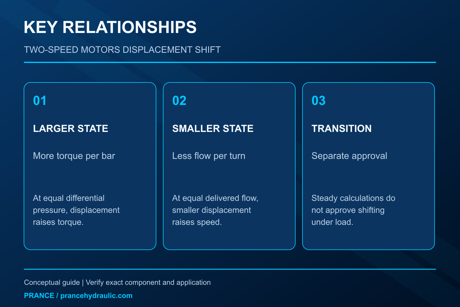
Two-speed hydraulic motor displacement switching changes the oil volume required for one shaft revolution. At the same delivered flow, reducing displacement raises the theoretical speed and reduces the torque available at the same pressure difference. A safe change therefore depends on the load, permitted motor speed, control supply, and machine braking strategy. A two-position command is not permission to shift under any load. Confirm the exact motor and control instructions before commissioning or changing a switching threshold.
This article explains the change between two approved displacement states. It does not provide a universal switching pressure, replacement control setting, or road-speed modification.
What “two-speed” means at the motor
A two-speed hydraulic drive can obtain two speed ranges by commanding two displacement states. The larger state normally provides greater torque for a given pressure difference, while the smaller state needs less inlet volume per revolution. Actual speed also depends on delivered flow, leakage, and load. The labels “low” and “high” describe the resulting range, not necessarily the electrical state of a solenoid.
A variable-displacement motor may have a two-point control, a proportional control, an automatic pressure-dependent control, or a combination. Two switches on a machine do not identify the motor mechanism. Some machines obtain speed ranges through pump control or a gearbox instead. Establish where the ratio change occurs before diagnosing the motor.
For a Prance A6VM-family enquiry, the relevant connection is a variable-displacement piston-motor application. The product family alone does not establish two-point control, displacement endpoints, or permitted switching conditions for the unit offered. These require the complete order code and approved documentation. Do not infer the selected option from a catalog photograph.
Calculate both steady states before considering the transition
For an ideal motor, speed in revolutions per minute is delivered flow in liters per minute multiplied by 1,000 and divided by displacement in cubic centimeters per revolution. With a stated volumetric efficiency, an approximate motor-speed calculation is n = 1,000 × Q × ηv / Vg. Use efficiency data for the actual operating point rather than borrowing a single catalog value from a different condition.
Ideal torque in newton meters is approximately Δp × Vg / 62.83 when pressure difference is in bar and displacement is in cubic centimeters per revolution. Approximate shaft torque includes the applicable mechanical efficiency. Pressure difference means inlet pressure minus outlet pressure; inlet gauge pressure alone can overstate the useful differential when the return side is pressurized.
These relationships follow conservation of volume and the pressure-displacement torque relation described in the MathWorks motor model. That model also separates leakage and friction. Its default parameters and numerical transition thresholds are simulation inputs, not switching approvals or ratings for a physical motor.
An illustrative displacement change
Assume a hypothetical motor receives 60 L/min and switches between 80 and 40 cm³/rev. Ignore losses only to make the relationship visible. The ideal speeds are 750 and 1,500 rpm. At a fixed pressure difference of 160 bar, the ideal torques are about 204 and 102 N·m. These values are an example, not Prance product specifications.
The smaller state therefore cannot provide the original torque at the same pressure difference. In the ideal calculation, maintaining about 204 N·m at 40 cm³/rev would require roughly 320 bar. This is not a recommendation to raise pressure. If the required pressure exceeds an approved limit, the smaller state is unsuitable for that load even though it offers an attractive no-load speed.
| Example condition | Displacement | Flow | Ideal speed | Ideal torque at 160 bar differential | Engineering implication |
|---|---|---|---|---|---|
| Larger state | 80 cm³/rev | 60 L/min | 750 rpm | About 204 N·m | Greater torque per bar |
| Smaller state | 40 cm³/rev | 60 L/min | 1,500 rpm | About 102 N·m | Higher speed but lower torque per bar |
| Smaller state with original torque demand | 40 cm³/rev | Flow must match resulting speed | Not established by torque alone | About 204 N·m would need about 320 bar ideally | Check limits; do not increase pressure to force the shift |
The table assumes steady conditions and neglects leakage, friction, acceleration, and circuit interactions. Its purpose is to reject a bad operating point before testing, not to predict the transient peak pressure or final loaded speed.
Why the actual speed may not double
A displacement ratio of two does not guarantee a speed ratio of two in service. The pump may reach a power or flow limit as pressure rises. Other branches may take flow, the controller may deliberately reduce pump delivery, or leakage may change with pressure and temperature. Measure motor-branch flow rather than assuming the pump’s nameplate flow reaches the motor.
There is also a distinction between motor-shaft speed and machine speed. A gearbox, wheel diameter, belt ratio, or slipping mechanical connection can alter the observed result. Use the same measurement boundary for both displacement states. A machine display may show a calculated travel speed rather than a measured motor speed.
If shaft speed increases little after the command changes, first check whether displacement actually changed and whether the available flow remained comparable. Do not immediately condemn the motor. Conversely, a large speed increase under a light load does not establish adequate torque or safe switching under the worst operating load.
The transition has its own limits
During a change in displacement, the rotating system has inertia and the hydraulic circuit has compliance. Shaft speed cannot instantaneously jump from one steady value to another. The mismatch between incoming flow, changing displacement, and mechanical acceleration can produce pressure excursions or an unexpected acceleration rate.
A change toward larger displacement can require more oil at the existing speed. In some conditions the driven load continues turning and the hydraulic unit can enter a pumping regime. A change toward smaller displacement can reduce torque capacity while the load still demands the previous torque. The circuit must manage these conditions through its approved control and protection arrangement.
For this reason, use the manufacturer’s permitted switching envelope, including any restrictions on load, pressure, speed, temperature, and direction. A steady-state calculation cannot establish that envelope. Never create a test by bypassing a brake valve, disabling an interlock, or increasing a relief setting until the machine completes the shift.
Pilot supply and electrical command are different evidence
Some displacement controls require hydraulic pressure to move the control mechanism, even when the operator selects the state electrically. A valid electrical command can coexist with inadequate control pressure, a restricted pilot path, or a control arrangement that has not met its enabling conditions. The minimum supply and its connection are specific to the exact control.
Read the schematic to identify where control pressure originates and whether it is internal or external. Do not assume that motor inlet pressure and control pressure are interchangeable measurements. A supply that is adequate during one direction of operation may behave differently during another, depending on the circuit.
For an electrical control, verify the commanded state, permitted supply, connector, and any feedback through approved test points. Do not assign “energized equals small displacement” from general experience. The intended default and energized states must come from the particular wiring and control diagram, especially where a default state affects vehicle handling.
Coordinate displacement with brakes and overrunning loads
A hydraulic motor that drives a suspended load, winch, or downhill travel function needs a reviewed braking strategy. Selecting a larger displacement is not a substitute for a mechanical brake or a correctly specified load-control circuit. The load may drive the motor after the pump command decreases, and the resulting flow and pressure must have a controlled path.
Review brake release, deceleration, anti-cavitation provisions, and displacement sequencing together. Their timing must come from the machine design. A successful shift on level ground without load does not prove that the same sequence is safe on a slope or with a suspended load.
Before inspection, immobilize the machine, support loads mechanically, isolate all energy sources, and verify stored energy is released using the approved method. NIOSH hazardous-energy guidance applies to this preparation. Do not rely on a selected speed range or an unpowered valve to hold a load while someone works on the drive.
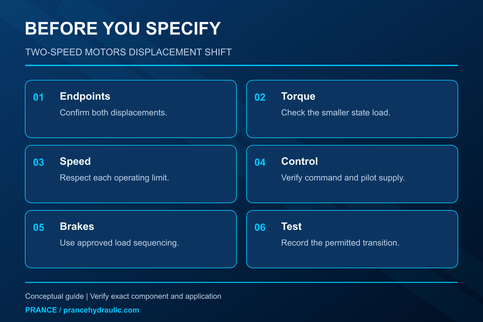
Diagnose a failed or harsh range change
Begin with a precise description: no change, delayed change, pressure spike, speed surge, or inability to carry the load in the smaller state. Note whether the problem occurs in both directions and whether it began after maintenance, a controller update, or a motor replacement. Those distinctions help separate an incorrect configuration from wear or supply trouble.
Compare command timing, actual shaft speed, motor-branch flow, both working-port pressures, and the permitted control-pressure measurement. Use synchronized records if the event is brief. A slow gauge and a display refreshed once per second can miss the relationship between a command and the resulting transient.
If the command changes but the hydraulic state does not, investigate enabling conditions and control supply through the approved procedure. If displacement changes but pressure rises toward a limit and speed falls, reassess torque demand and available power. If a shift is harsh, examine the specified sequencing and response arrangement instead of adding a generic time delay or changing an internal restriction.
Choose the switching point from the complete duty
The useful switching point is constrained by the available torque in the smaller state and the speed limit in either state. Plot or tabulate the machine’s required torque and speed against the permitted motor operating data. Include acceleration, cold operation, and the highest credible load, not just the normal unloaded travel condition.
A controller may use load-related pressure as one input, but pressure alone does not describe every hazard. Return pressure affects the useful differential, and rapid load changes can occur before a steady pressure threshold gives a reliable indication. An automatic threshold or hysteresis band therefore belongs to the machine’s validated control strategy.
For procurement, specify both displacement endpoints, continuous and transient duty, permitted shaft speed, load inertia, control supply, braking arrangement, and required default state. Ask the supplier to confirm the exact option and switching conditions. This gives a clearer acceptance criterion than asking for “a two-speed motor” with matching mounting dimensions.
Verify the result within an approved test plan
After repair or configuration confirmation, qualified personnel should repeat the permitted test in stages. Confirm state identification and command behavior before progressing to the authorized load conditions. Record speed and pressure response during both permitted transitions, and stop at the first unexpected movement, limit approach, or abnormal leakage.
Compare the measured steady states with the expected flow-displacement relationship while accounting for actual efficiency and temperature. Then compare transient behavior with the machine’s acceptance criteria. Keep these two results separate: a motor can reach the expected final speed while producing an unacceptable transition.
Document the final control code, approved settings, software version where applicable, and measured conditions. A replacement should be accepted against that complete configuration. Similar shaft dimensions and a successful no-load spin do not establish equivalent displacement control or safe load behavior.
Frequently asked questions
Does half the displacement always mean twice the speed?
Only in the ideal comparison at unchanged delivered flow. Real speed also depends on leakage, available pump flow, power limits, and load. Check the actual motor speed limit before treating the theoretical ratio as an allowable operating point.
Can a two-speed motor switch under full load?
Only if the exact motor control and machine design permit that condition. There is no universal approval. Smaller displacement reduces torque per bar, and the transition may impose additional pressure and acceleration demands.
Is the energized solenoid always the high-speed state?
No. The default and energized states depend on the control arrangement and wiring. Identify them from the complete order code and approved diagram. Do not infer a safe state from another motor series.
Why does the motor stall after selecting high speed?
The smaller displacement may require more pressure than the circuit can safely provide for the load, or available flow and power may fall. Confirm the displacement state, pressure differential, and branch flow before assigning the cause to motor wear.
Can displacement switching replace a load-holding brake?
No. A displacement command is not an independent means of securing an overrunning or suspended load. Use the specified mechanical support, brake, and hydraulic load-control arrangement, with sequencing validated for the machine.
Product and related engineering resources
The Hydraulic High Pressure Piston Motor A6VM is the relevant product category for this guide. The illustrations explain concepts and do not depict the product internals or establish operating limits. Confirm the complete code and approved documentation. Related resources: Hydraulic High Pressure Piston Motor A6VM, hydraulic motor range, How should torque and speed shape a hydraulic motor review?, When does a variable or fixed displacement motor fit?.
Sources and limits of this guide
University and primary technical sources support general principles only. Product ratings, control options and permitted settings require the exact ordered configuration and its approved documentation.
- NPTEL: Fundamentals of Industrial Oil Hydraulics and Pneumatics
- NIOSH: preventing injuries from hazardous energy
- MathWorks: variable-displacement motor equations and loss model
University lesson: operating principles
NPTEL-NOC IITM presents 6.3 – Hydraulic Motors. The lesson supports the motor displacement, flow and torque relations used in this discussion; it is not a model-specific performance or installation approval.