Wenzhou Prance Hydraulic Equipment Co., Ltd.

Proportional Valve PWM Frequency: Switching Frequency vs Dither
Proportional valve PWM frequency is a driver setting whose meaning must be identified before choosing a value. It may describe the switching used to regulate coil current, an intentionally imposed low-frequency oscillation, or an external command accepted by an electronic module. These are different functions. There is no universal frequency suitable for every proportional valve. Use the complete valve code and compatible driver’s documentation to establish the permitted settings, then evaluate current behavior, response, heat, noise, and motion under controlled conditions. Do not apply a bare-coil PWM output to an integrated-electronics valve merely because both devices are called proportional valves.
Identify which electrical interface you have
Start with the complete valve and amplifier identification. Some valves expose coils intended for a compatible current-regulating driver. Others include electronics and accept a specified analog, digital, or other command interface. An external command is not automatically a direct coil-power input. Connector appearance, nominal supply voltage, and a similar product photograph cannot establish compatibility.
Separate power supply, command input, and coil-drive output in the documentation. The power supply provides energy. The command expresses the requested valve behavior. The driver controls coil current using its own circuitry and settings. A PWM command supported by a module may have a specified frequency and duty interpretation that differs from the module’s internal power switching.
The 4WRAE exterior illustrated here is a real catalog reference. It does not reveal the internal switching frequency, connector pin assignment, allowable command waveform, or tuning range of the ordered unit. Obtain the applicable manual before connecting test equipment or changing parameters. A generic online circuit cannot replace the full electrical specification.
Understand PWM switching and average current
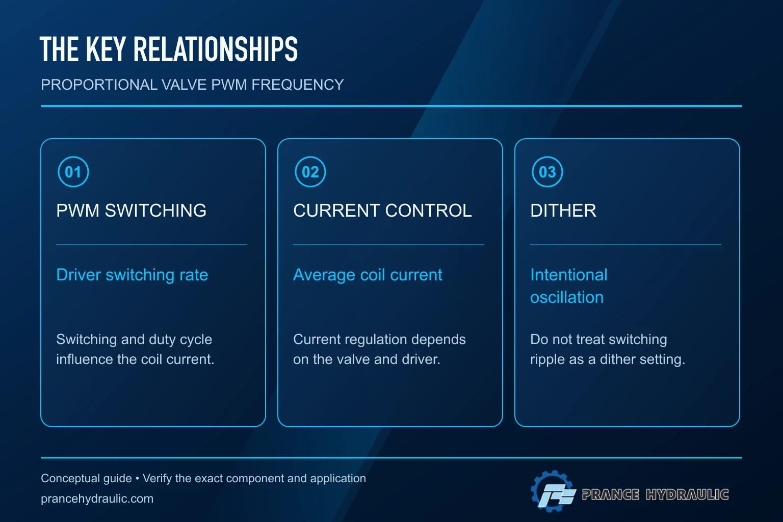
Pulse-width modulation switches a drive between states, with duty cycle describing the fraction of each cycle spent in a selected state. Switching frequency describes how often that cycle repeats. A solenoid coil’s inductance, resistance, supply conditions, and driver circuit affect how the resulting current changes during each cycle. Voltage duty alone does not establish a universal coil-current value.
A regulated current driver measures or otherwise controls current to follow a target within its operating limits. This matters because coil resistance changes with temperature and supply voltage may vary. An open-loop voltage-duty command can therefore produce different current as conditions change. For a proportional actuator, that difference can change the relationship between requested and actual behavior.
Avoid a misleading arithmetic shortcut: half duty at a stated supply is not proof of half rated current or half valve opening. The electrical response, magnetic force, spring forces, friction, hydraulic forces, and valve geometry all contribute. Use the manufacturer’s command scaling and control information rather than assuming a linear chain from duty cycle to flow.
Distinguish intentional dither from switching ripple
Dither is an intentional oscillation used in some proportional controls to reduce the effect of friction and hysteresis. It has a defined amplitude and frequency, and its suitability depends on the actuator and application. PWM switching can create current ripple, but incidental ripple is not automatically the same as a deliberately specified dither function.
Some driver designs use a switching regime whose ripple also contributes to dither-like behavior. Other designs regulate current with a separate dither signal superimposed on the target. These arrangements explain why different manuals use frequency terms differently. Read the actual control description before deciding that one setting can replace another.
Excessive or unsuitable oscillation can introduce unwanted motion, pressure fluctuation, noise, or heating. Too little may fail to produce the intended friction-related improvement. This article does not prescribe dither amplitude or a tuning procedure for a particular valve. The task is first to identify which parameter is being discussed and which documentation governs it.
Why a higher frequency is not automatically better
Increasing switching frequency can alter current ripple and shift electrical or acoustic behavior. It can also affect driver switching losses and the available current-control performance. The result depends on the complete drive circuit, coil, supply, and control strategy. A number chosen from another valve family can therefore produce an unsuitable result even when the nominal voltage is the same.
At a lower switching frequency, current ripple may become more pronounced in some circuits. Whether that ripple helps friction behavior or causes objectionable pressure and motion variation depends on the application. There is no safe inference that all low frequencies are correct dither or that all high frequencies eliminate hydraulic disturbance.
The switching stage, flyback arrangement, current measurement, and protective functions also matter. Do not redesign the output stage by adding an unreviewed diode, capacitor, or filter to suppress noise. Such changes can affect current decay, response, and protection. Use the approved driver configuration and request manufacturer guidance for a persistent problem.
Separate frequency from duty, amplitude, and command rate
Frequency is measured in cycles per second. Duty cycle is a fraction of a switching period. Dither amplitude describes the size of an intended oscillation. Command update rate describes how often a controller supplies new requested values. These quantities can interact but do not describe the same thing. Keep each name and unit explicit in the specification.
For a hypothetical timing example, a 200 Hz waveform has a 5 ms period because period equals one divided by frequency. A 40 percent duty would select an on-time of 2 ms in that simplified waveform definition. These numbers illustrate timing only. They do not recommend 200 Hz, establish coil current, or predict a valve opening.
If a PLC or controller offers an output described as PWM, verify electrical level, current capability, frequency range, resolution, isolation, and the intended receiving input. A controller’s PWM signal output may be intended to command an amplifier rather than supply a valve coil. Match both ends of the interface before discussing hydraulic tuning.
Build a compatibility checklist before commissioning
Use the following qualitative table to distinguish the questions that must be answered. Parameter limits come from the ordered valve and driver documentation; no numerical entry in this table is a product setting or recommendation.
| Artikel | Verlangte Beweismittel | Common mistaken assumption |
|---|---|---|
| Valve interface | Complete code and electrical manual | Every proportional valve accepts direct PWM power |
| Driver output | Supported coil type and current regulation | Matching supply voltage proves compatibility |
| Switching frequency | Permitted range and parameter definition | A forum value applies to every valve |
| Dither | Supported function, amplitude and frequency rules | Any current ripple is approved dither |
| Command input | Signal type, scaling and fault behavior | PWM input and coil PWM are interchangeable |
| Thermal behavior | Driver and valve operating limits | Quiet operation proves acceptable heating |
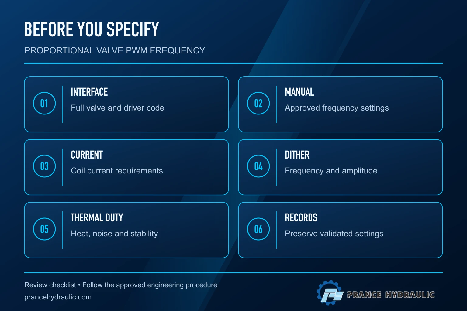
Record document revisions and the settings actually loaded into the driver. A default configuration is not necessarily correct for a replacement valve or a different coil option. Where a parameter is fixed internally, do not treat the absence of an adjustment as missing functionality or try to impose an external switching signal.
Investigate symptoms without changing everything
For buzzing, erratic low-speed motion, pressure fluctuation, weak response, or rising temperature, first confirm whether the electrical configuration matches the approved combination. Check supply condition, command scaling, grounding and shielding as specified, current regulation status, and any recorded faults. Then examine hydraulic causes such as air, contamination, load changes, and pressure conditions.
A symptom does not identify frequency as the cause. A noisy valve can still have an unrelated hydraulic disturbance; a quiet valve can still be incorrectly driven. Compare the command, current-related information available from the approved driver, and hydraulic response. Use suitable instruments and qualified personnel, especially where switching measurements can be misinterpreted by ordinary meters.
Preserve the original settings and change only a documented parameter within its permitted range using an approved test procedure. Define limits for motion, pressure, temperature, and unexpected behavior before testing. Do not continue a trial merely because a new setting appears smoother at one operating point. Check the full permitted working cycle and the defined fault response.
Evaluate heat, response, and operating stability together
Assess the driver and coil over the relevant duty duration. A short bench trial may miss heating that appears during extended operation. Record oil and ambient conditions, command level, operating duration, supply behavior, and the manufacturer’s temperature or current indicators where available. Do not estimate a winding temperature from external touch.
Review response at the minimum useful command, across ordinary operating points, and during approved command transitions. A setting that reduces one audible tone may worsen low-flow control or change the motion response. If the system includes a closed control loop, frequency-related changes can interact with the controller and must be evaluated by someone responsible for that loop.
Fault behavior is part of acceptance. Confirm how the system responds to loss of command, supply interruption, communication fault where applicable, and an emergency stop under the equipment’s design. Do not assume zero duty creates a safe hydraulic state. The valve’s neutral behavior, trapped pressure, external loads, and stored energy remain circuit-level considerations.
Specify the purchase and preserve the final record
For an RFQ or replacement review, provide the full valve code, driver model and revision, coil information, supply conditions, command interface, operating pressure and flow range, and required response. Ask the supplier to distinguish command-frequency requirements, internal switching, and adjustable dither. Request the applicable configuration file or parameter list when it is part of the supplied system.
Keep the final documented settings, revisions, test conditions, observations, and unresolved limits with the machine record. This makes later replacement and troubleshooting more reliable. If the available documentation cannot establish compatibility, obtain the missing evidence before operation rather than copying another machine’s frequency.
Before electrical work or hydraulic inspection, follow the equipment’s isolation procedure and verify stored energy is controlled. NIOSH guidance supports this hazardous-energy discipline. Removing the command or silencing the coil is not evidence that an actuator cannot move or that a pressurized line is safe to open.
Häufig gestellte Fragen
What is the best PWM frequency for a proportional valve?
There is no universal best value. Identify whether the term refers to a command input, coil switching, or a dither-related setting, then use the documented valve and driver combination and its permitted operating conditions.
Is PWM frequency the same as dither frequency?
Not necessarily. A driver may use switching ripple, a separately generated dither signal, or another control arrangement. Read the manufacturer’s parameter definitions before treating the two settings as interchangeable.
Does increasing PWM frequency always reduce problems?
No. It can change ripple, losses, acoustic behavior, and current-control response. A smoother sound alone does not establish acceptable coil heating, hydraulic response, or compatibility with the driver.
Can a PLC PWM output drive any proportional valve directly?
No. Verify whether the output is a command signal or a suitable power stage and whether the valve expects a bare-coil driver or an input to integrated electronics. Current regulation and protection requirements still apply.
Can I copy settings from a similar-looking valve?
Appearance does not establish coil, electronics, command scaling, or tuning compatibility. Use the complete code and applicable manuals, preserve existing settings, and validate any approved change against the actual operating cycle.
Produktdaten und entsprechende technische Ressourcen
The Proportional Valve 4WRAE catalog exterior is used as the real product reference in these explanatory images. It does not establish the approved service method, optional construction, or operating limits for an individual order. Confirm the complete code and its documentation. Related resources: Proportionalventil 4WRAE, Hydraulikventilpalette, Hydraulikventil Dither: Reduzierung von Frequenz, Amplitude und Reibung, Hydraulische Ventil-Nulleinstellung: Servo- und Proportionalsteuerungen.
Sources and limits of this guide
University teaching supports physical and fluid-power principles; NIOSH supports hazardous-energy precautions. Calculations are hypothetical, not Prance ratings. The TI document, where linked, supports current-regulation principles only and is not a recommendation to use that circuit or its settings with the illustrated valve. No curve, pinout, attachment approval or model-specific frequency is inferred from the catalog exterior.
- Texas Instruments DRV110: PWM current regulation principles for solenoids; not a recommended valve driver or valve setting
- NPTEL Fluid Power Control: proportional valves and amplifiers
- NIOSH: hazardous-energy injury prevention
University lesson: operating principles
Jim Pytel presents Acceleration Control Using Proportional Valves (Full Lecture). The lesson supports the proportional valve and amplifier operating principles; PWM and dither settings require the ordered driver documentation used in this discussion; it is not a model-specific performance or installation approval.