Wenzhou Prance Hydraulic Equipment Co., Ltd.

Einschaltdauer der hydraulischen Magnetspule: Dauerbetrieb und intermittierende Betriebsarten
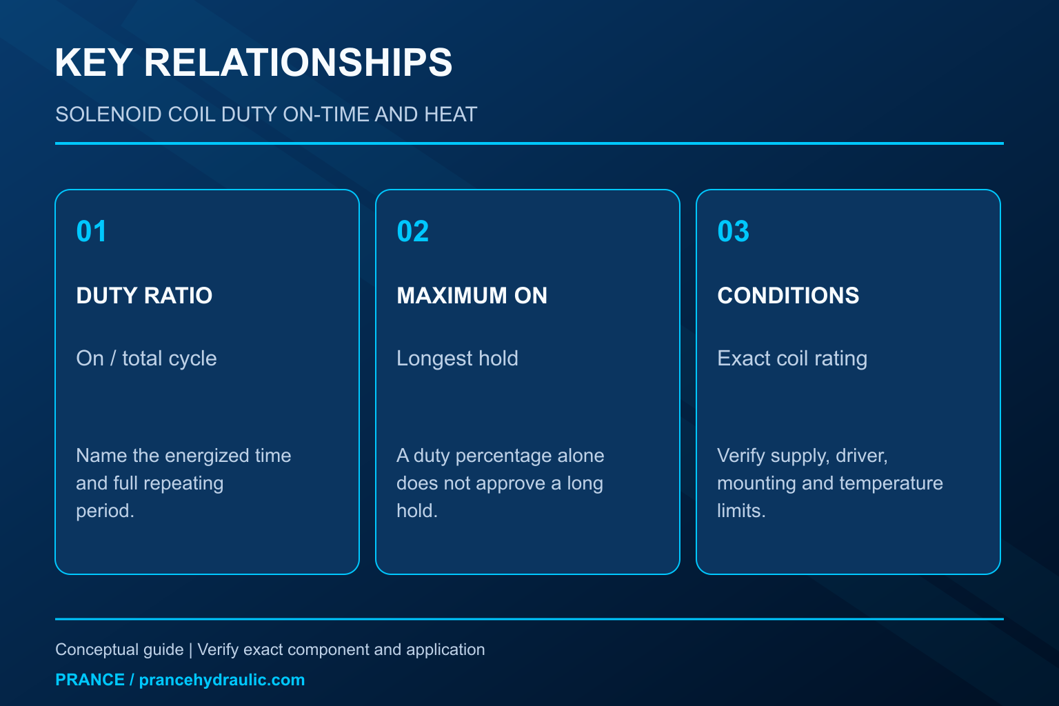
Hydraulic solenoid coil duty cycle is the proportion of an operating cycle during which the coil is energized. Calculate it as on-time divided by total on-time plus off-time, multiplied by 100 percent. That percentage is only part of the selection: maximum continuous on-time, supply voltage, ambient and fluid temperatures, mounting, and the exact coil rating also matter. A coil marked for intermittent operation cannot be assumed safe for a long continuous hold simply because the machine is idle for the rest of the shift.
Use the complete coil and valve documentation to establish the permitted duty. This guide explains thermal duty and selection checks; it does not assign an unverified rating to a Prance valve.
Read the percentage together with the operating conditions
The abbreviation ED is used for relative energization duration in many solenoid documents. A 100% ED or continuous-duty designation normally indicates suitability for continuous energization under the stated conditions. It does not mean that the coil stays cool, accepts any supply voltage, or can operate above its specified ambient limit.
An intermittent rating relies on periods without energization and on a defined cycle or maximum on-time. The same percentage can describe a short repeating pulse or a much longer heating period. Those patterns can produce different peak winding temperatures even though their arithmetic average is identical.
The US Navy’s NSWC mechanical reliability handbook, available from NASA, discusses coil self-heating and maximum on-time in its solenoid section. Its general lesson is that the percentage alone is insufficient. Do not transfer a numerical example or a thermal assumption from that handbook to a particular valve coil as a product rating.
Calculate the actual command pattern
For a repeating cycle, ED (%) = ton / (ton + toff) × 100. Use consistent time units. If a hypothetical coil is on for 15 seconds and off for 45 seconds, the calculated duty is 25%. That calculation describes the command pattern; it does not show whether a particular coil is approved for it.
Now compare 15 minutes on and 45 minutes off. This is also 25%, but the uninterrupted heating period is sixty times longer. A coil approved for a short 25% cycle may not tolerate that long hold. The allowed cycle period and maximum on-time must be checked separately.
For an irregular machine cycle, record the longest uninterrupted energization and representative repeated sequences, including restart behavior. A daily average can hide the worst condition. An operator holding a function during setup, a stalled sequence, or a fault that leaves an output on may create a different duty from the normal automatic cycle.
Continuous duty still produces heat
An energized winding dissipates electrical power and transfers heat into its surroundings. Its final temperature depends on both heat generation and heat removal. The surrounding air, nearby hot equipment, the valve and fluid temperature, and the permitted mounting arrangement all influence that balance.
A coil can therefore feel hot during normal service, but touch is not an acceptance test. The permitted surface and winding temperatures are different quantities, and neither can be established from discomfort or appearance. Personnel should avoid burns and use the manufacturer’s specified measurement method where a temperature investigation is needed.
Conversely, a coil that feels cooler than another is not automatically better matched. Different designs, supplies, operating times, and mounting conditions can produce different surface temperatures. Compare like-for-like duty and documented limits rather than selecting a replacement by how cool its outer cover feels.
Separate DC power, AC behavior, and current-controlled drive
For a simple DC winding at a defined condition, electrical power is P = V × I, and P = I²R. The resistance changes with temperature, so a cold resistance measurement does not directly describe the hot operating current. Use the rated voltage and applicable hot or cold data as identified in the coil documentation.
A hypothetical 24 V DC winding drawing 1 A dissipates 24 W at that operating point. This is an arithmetic example, not a valve specification or a temperature prediction. Multiplying that value by a duty fraction can estimate average electrical input only under the stated assumptions; it does not establish the peak winding temperature or permitted on-time.
AC coils can have different pull-in and holding behavior. A current-regulated driver or an electronically reduced holding current creates another case. Do not apply a simple DC resistance calculation to an AC coil or assume that an electronic driver makes any intermittent coil suitable for continuous service. The complete coil-driver combination must be approved.
PWM duty is a different time scale
A driver may switch voltage rapidly using pulse-width modulation while the machine commands a valve continuously. The PWM percentage describes the switching waveform, while the machine’s thermal duty describes the longer energized operating pattern. Calling both values “duty cycle” without naming the time scale creates selection errors.
Current ripple, switching frequency, current regulation, and any pull-in/hold strategy affect electrical input and magnetic force. A 50% PWM command does not universally mean half the rated current or half the heating. The relationship depends on the winding, supply, driver, and operating state.
For a proportional valve, follow the specified amplifier and current command limits. For an on/off valve using an approved power-reduction driver, retain the documented pull-in and holding behavior. A generic PWM module is not a validated repair for a hot coil, especially if reduced force could prevent complete switching or alter the fail-safe response.
Match the rating to the application
Use the following qualitative table to decide what must be confirmed. It is a selection guide rather than a product parameter table. A missing rating is an unresolved specification, not evidence that the coil accepts the most demanding condition.
| Application condition | Information required | What the evidence must establish | Unsafe assumption |
|---|---|---|---|
| Function remains energized for long periods | Continuous-duty designation and stated environment | Approved continuous operation for the exact coil and supply | Any hydraulic coil can remain on indefinitely |
| Short repeating operation | Relative duty, cycle period, maximum on-time | Actual sequence fits every relevant timing limit | Equal percentages mean equal temperatures |
| Hot enclosure or hot fluid | Ambient, medium, and mounting limits | Combined thermal conditions are within approval | Insulation class alone allows the enclosure temperature |
| cURL Too many subrequests by single Worker invocation. To configure this limit, refer to https://developers.cloudflare.com/workers/wrangler/configuration/#limits | cURL Too many subrequests by single Worker invocation. To configure this limit, refer to https://developers.cloudflare.com/workers/wrangler/configuration/#limits | cURL Too many subrequests by single Worker invocation. To configure this limit, refer to https://developers.cloudflare.com/workers/wrangler/configuration/#limits | cURL Too many subrequests by single Worker invocation. To configure this limit, refer to https://developers.cloudflare.com/workers/wrangler/configuration/#limits |
| cURL Too many subrequests by single Worker invocation. To configure this limit, refer to https://developers.cloudflare.com/workers/wrangler/configuration/#limits | cURL Too many subrequests by single Worker invocation. To configure this limit, refer to https://developers.cloudflare.com/workers/wrangler/configuration/#limits | cURL Too many subrequests by single Worker invocation. To configure this limit, refer to https://developers.cloudflare.com/workers/wrangler/configuration/#limits | cURL Too many subrequests by single Worker invocation. To configure this limit, refer to https://developers.cloudflare.com/workers/wrangler/configuration/#limits |
cURL Too many subrequests by single Worker invocation. To configure this limit, refer to https://developers.cloudflare.com/workers/wrangler/configuration/#limits.
Insulation class and protection rating answer different questions
Insulation temperature class concerns the winding insulation system. It is not a universal permitted ambient temperature, and it does not remove limits on encapsulation, connectors, seals, or the surrounding assembly. A label showing a higher insulation class is insufficient evidence that a replacement will tolerate a hotter installation.
An ingress-protection designation addresses specified exposure conditions for the assembled arrangement. It does not establish the thermal duty of the winding. The connector, seals, cable entry, and correct assembly can be part of that protection, so an unplugged or incorrectly fitted connector may not provide the stated condition.
Voltage and frequency are also separate requirements. A 24 V marking without the correct AC/DC designation does not identify an interchangeable coil. Include suppression components, polarity where relevant, and the approved driver when matching the complete electrical arrangement.
Investigate overheating without removing the coil live
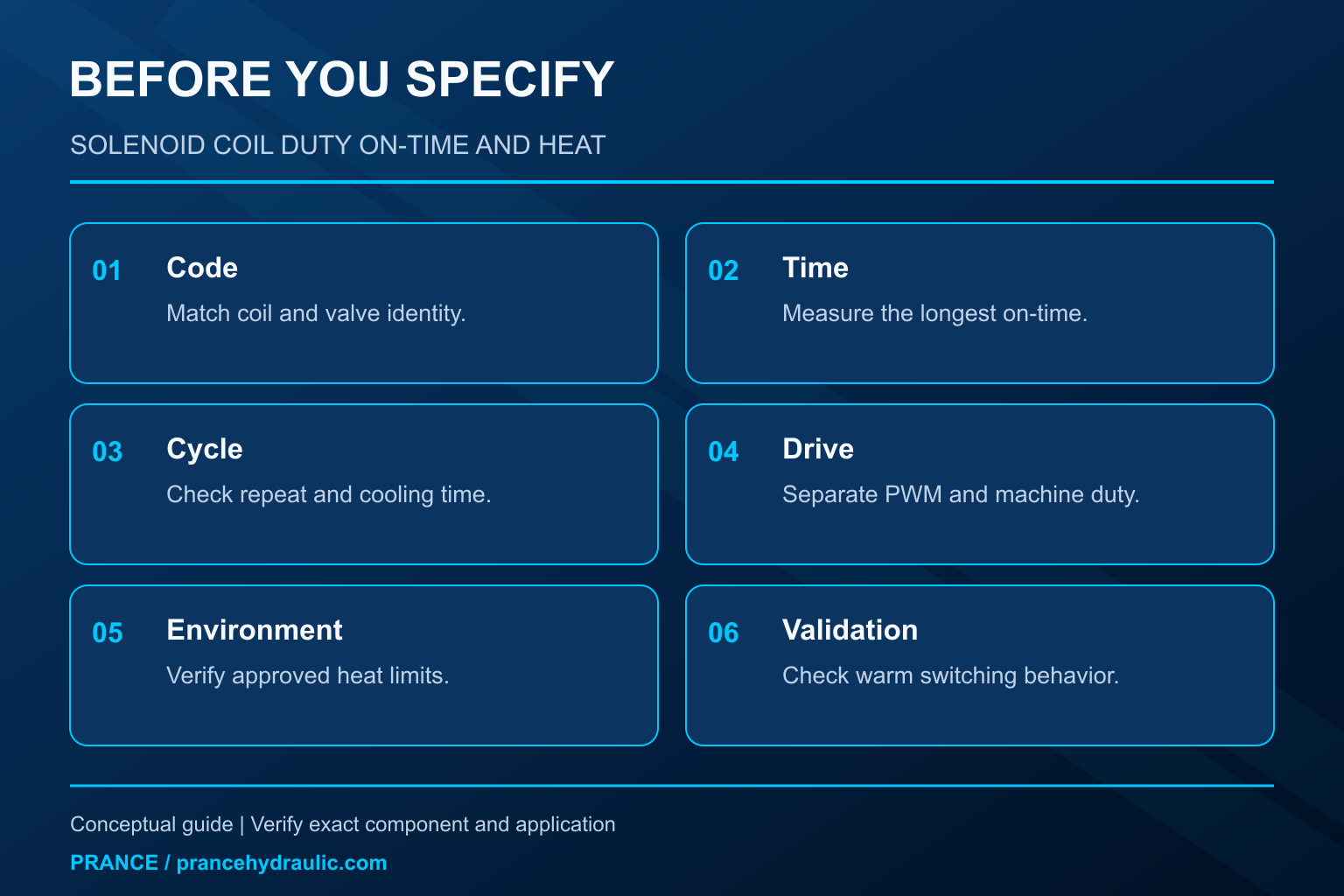
Begin by identifying the exact coil and its rating. Compare the actual command sequence with the intended duty, including setup, cleaning, manual operation, and faults. Review whether a recent control-program change has extended the on-time or removed the cooling interval.
With the machine safely isolated, inspect the connector, wiring identification, mechanical assembly, and evidence of damage. Hydraulic pressure and electrical energy both require control. Secure loads, account for stored pressure, and follow the NIOSH hazardous-energy principles and machine procedure before touching the assembly.
Qualified personnel can then measure the permitted electrical quantities and temperatures through the approved procedure. Do not energize a loose coil off its intended valve assembly unless the manufacturer explicitly permits that test. Changing the magnetic path or thermal mounting can make the test misleading or damage the component.
If the actual voltage, current, duty, or surrounding temperature exceeds approval, correct that demonstrated condition before installing another identical coil. If those conditions are correct but heating or switching remains abnormal, seek a configuration-specific investigation. A resistance reading alone cannot prove insulation health, correct magnetic force, or acceptable continuous duty.
Account for both coils and the valve state
A double-solenoid valve requires the intended command logic for its exact spool and control arrangement. Do not assume both coils may remain energized together because each individual coil has a continuous rating. Simultaneous commands can create an undefined or prohibited operating condition depending on the valve and electronics.
Similarly, de-energizing a coil does not universally mean the machine becomes safe. Spring-centered, spring-return, and detented arrangements can produce different valve states, and a hydraulic actuator may still be driven by stored energy or gravity. Establish the actual fail-safe behavior through the machine design.
This is why duty selection must remain connected to switching reliability. Reducing on-time or holding current to improve temperature is unacceptable if it prevents a commanded state from being maintained or defeats an approved safety function. Any revised drive method needs documented compatibility and machine-level validation.
Specify the replacement and verify it in service
For a Prance 4WE-related enquiry, provide the full valve and coil codes, rated supply and frequency, driver type, connector details, longest on-time, repeating cycle, and surrounding temperature range. A confirmed model identification applies only to that reference product; it does not prove the duty rating of another coil or variant.
Ask for the duty designation and its conditions in the applicable document. Where the installation is unusual, describe the hot enclosure, shared mounting, or current-reduction system explicitly. Do not accept a generic statement such as “continuous coil” without confirming which coil code and environment it covers.
After an approved replacement, verify switching in the permitted cold and warm operating conditions. Confirm the actual command pattern, supply, and measured temperature against the applicable criteria. Check for connector damage, unexpected motion, and failure to return to the intended state. Stop the test if there is smoke, insulation odor, leakage, or abnormal operation.
Keep the confirmed component code and measured operating conditions with the maintenance record. This prevents the next replacement from being chosen only by physical fit and voltage. The useful outcome is a coil that performs the required switching duty within its documented electrical and thermal limits.
Häufig gestellte Fragen
Does 100% ED mean the coil will remain cool?
No. Continuous energization still generates heat. The designation applies under specified electrical, mounting, and environmental conditions. Use the documented limits and measurement method; do not judge suitability by touch.
Can I use daily average on-time to calculate duty?
A daily average may hide a damaging long hold or repeated hot cycle. Identify the maximum uninterrupted on-time and the applicable repeating sequence. Compare both with the exact coil’s duty and cycle-period limits.
Is 25% duty with a long cycle equivalent to short pulses?
Not necessarily. Equal percentages can produce different peak temperatures because the uninterrupted heating and cooling periods differ. The manufacturer’s maximum on-time and cycle definition must also be satisfied.
Does a 50% PWM output mean 50% thermal duty?
No. PWM describes a rapid electrical waveform, while application duty describes the longer operating sequence. Current regulation, frequency, winding behavior, and pull-in/hold control determine the actual electrical and thermal result.
Can a higher insulation class replace duty verification?
No. Insulation class does not establish the complete coil’s ambient, connector, encapsulation, mounting, or maximum on-time limits. Match the full coil and driver specification to the application rather than relying on one label.
Produktdaten und entsprechende technische Ressourcen
The Directional Valve 4WE is the relevant product category for this guide. The illustrations explain concepts and do not depict the product internals or establish operating limits. Confirm the complete code and approved documentation. Related resources: Wegeventil 4WE, Hydraulikpumpen-Sortiment, Test der Hydraulik-Magnetspulenwiderstandsfähigkeit: Ohm und Temperatur, AC- vs. DC-Hydraulik-Magnetventile: Zuleitung, Einschaltstrom und Ersatz.
Sources and limits of this guide
University and primary technical sources support general principles only. Product ratings, control options and permitted settings require the exact ordered configuration and its approved documentation.
- NPTEL: Grundlagen der industriellen Ölhydraulik und Pneumatik
- NIOSH: Verletzungen durch gefährliche Energie verhindern
- US Navy NSWC-10 mechanical reliability handbook, section 5.3: solenoid heating and maximum on-time
University lesson: operating principles
NPTEL-NOC IITM presents 5.4 – Directional Control Valves. The lesson supports the solenoid-operated hydraulic directional-valve principles used in this discussion; it is not a model-specific performance or installation approval.