Wenzhou Prance Hydraulic Equipment Co., Ltd

Hydraulic Roller Drives: From Line Speed and Traction to Motor Size
Hydraulic motor roller drive selection starts with the force and surface speed required at the roller, not with motor displacement alone. Convert line speed into roller speed, convert tangential force into torque, then account for gearing, acceleration, losses and the hydraulic supply. A winding roll needs particular care because its effective radius changes during production: the motor may need its highest speed near the core and its highest steady torque near the full roll. A motor chosen from only one of those points can miss the other. This guide gives calculation examples and decision boundaries without treating assumed values as product ratings.
Decide whether the drive is a fixed roller or a growing roll
A fixed-diameter process roller presents a substantially constant working radius. A center-driven winding roll changes radius as material accumulates. A surface-driven winder introduces another relationship because traction at the contact drives the roll. Identify the arrangement before applying a speed or torque formula.
For a driven process roller between web spans, the net tangential force depends on the tension difference across it, together with friction and other mechanical effects. It is not automatically the full tension in either span. A center winder pulling from a comparatively slack upstream path presents a different balance.
The Cleveland State University research cited below develops roller and web-tension dynamics. This article uses elementary force, torque and speed relationships for initial selection. It does not reproduce a complete web-control model or imply that a single pressure setting can manage every material and winding condition.
Convert line speed to rotational speed
With line speed v in meters per minute and effective roller radius r in meters, roller speed n in revolutions per minute is n = v / (2 × pi × r), assuming the surface and material move together without slip. Use the loaded working radius where a compliant cover materially changes it.
For an illustrative line speed of 30 meters per minute and radius of 0.05 meters, the required roller speed is about 95.5 revolutions per minute. At a radius of 0.15 meters with the same line speed, speed falls to about 31.8 revolutions per minute. These are assumed geometry and process inputs, not BMP motor operating points.
Check both endpoints and any threading, jogging or overspeed requirement. A motor with sufficient maximum speed may still run unevenly at the low end of the intended range. Request data for the actual motor configuration and control conditions rather than assuming that any orbital motor will provide the required low-speed quality.
Convert the tangential force into torque
For a simple steady force applied tangentially at radius r, roller torque is T = F × r, with force F in newtons and torque T in newton-meters. For a center winder, the relevant web force depends on the tension specification and arrangement. If tension is given per unit width, first convert it into total force using the actual web width.
Assume a 200 newton effective tangential force. At a 0.05 meter radius, steady process torque is 10 newton-meters. At 0.15 meters, it is 30 newton-meters. Thus the larger roll requires more torque while rotating more slowly at the same line speed.
This elementary result does not include bearing friction, seal drag, acceleration or a gearbox. It also does not establish permissible material tension. Use a force requirement derived from the process and product quality limits; increasing torque until the web stops slipping can stretch or damage material before the drive reaches a mechanical limit.
Check the power relationship as a consistency test
Mechanical process power is P = F × v when force and speed use consistent units. With the illustrative 200 newtons and 30 meters per minute, convert speed to 0.5 meters per second. The resulting process power is 100 watts, before mechanical and hydraulic losses.
The same result follows from torque multiplied by angular speed. At the small radius, torque is lower and speed higher; at the large radius, torque is higher and speed lower. For the assumed constant force and line speed, their product remains the same. This provides a useful check against a missing factor of 60 or an incorrect radius unit.
Constant process power does not mean constant required hydraulic flow or constant pressure. A fixed-displacement motor changes speed mainly with supplied flow, while the pressure difference required to produce torque changes with load and efficiency. Include the complete operating range when reviewing the supply and control valve.
Translate roller duty through the gearbox
Define gearbox ratio i as motor speed divided by roller speed. Motor speed is then i times roller speed. For a driving gearbox with efficiency eta_g, the motor torque needed for the specified roller torque is approximately T_motor = T_roller / (i × eta_g). This convention must be stated because ratio notation is not universal.
If an illustrative 3:1 reduction has assumed efficiency of 0.90, 30 newton-meters at the roller requires about 11.1 newton-meters from the motor. Roller speed of 31.8 revolutions per minute corresponds to approximately 95.5 motor revolutions per minute. These figures exclude acceleration and do not recommend that ratio for a particular machine.
The ABB winder-control documentation in the references describes the same direction of speed and torque conversion. Use actual gearbox efficiency and load limits for selection. Check shaft alignment, reaction torque and access for maintenance in addition to the arithmetic.
Relate motor torque and speed to pressure and flow
For initial metric calculations, ideal motor torque in newton-meters is approximately pressure difference in bar multiplied by displacement in cubic centimeters per revolution, divided by 20 × pi. Available shaft torque is lower after the appropriate mechanical efficiency is included. Use motor pressure difference, not supply pressure alone, because outlet backpressure reduces the useful differential.
Ideal speed in revolutions per minute is 1,000 times flow in liters per minute divided by displacement in cubic centimeters per revolution. Leakage means actual speed differs from that ideal relationship. At a desired speed, required supplied flow must include the relevant volumetric-efficiency behavior.
These equations identify candidate displacement and supply requirements. They do not replace starting-torque data, minimum stable speed, case-pressure limits or continuous-duty ratings. Do not insert one convenient efficiency value and present the resulting answer as a guaranteed motor capability across the entire speed range.
Build an operating-point table
The table applies the elementary relationships above and the winding/gearing concepts in the cited university and ABB sources. Every numerical value is an illustrative assumption, not a product specification.
| Assumed condition | Radius | Line speed | Roller speed | Process force | Steady process torque |
|---|---|---|---|---|---|
| Near-core center winding | 0.05 m | 30 m/min | 95.5 rpm | 200 N | 10 Nm |
| Intermediate buildup | 0.10 m | 30 m/min | cURL Too many subrequests by single Worker invocation. To configure this limit, refer to https://developers.cloudflare.com/workers/wrangler/configuration/#limits | 200 N | cURL Too many subrequests by single Worker invocation. To configure this limit, refer to https://developers.cloudflare.com/workers/wrangler/configuration/#limits |
| cURL Too many subrequests by single Worker invocation. To configure this limit, refer to https://developers.cloudflare.com/workers/wrangler/configuration/#limits | cURL Too many subrequests by single Worker invocation. To configure this limit, refer to https://developers.cloudflare.com/workers/wrangler/configuration/#limits | 30 m/min | cURL Too many subrequests by single Worker invocation. To configure this limit, refer to https://developers.cloudflare.com/workers/wrangler/configuration/#limits | 200 N | cURL Too many subrequests by single Worker invocation. To configure this limit, refer to https://developers.cloudflare.com/workers/wrangler/configuration/#limits |
| cURL Too many subrequests by single Worker invocation. To configure this limit, refer to https://developers.cloudflare.com/workers/wrangler/configuration/#limits | 0.05 m | 30 m/min | 95.5 rpm | cURL Too many subrequests by single Worker invocation. To configure this limit, refer to https://developers.cloudflare.com/workers/wrangler/configuration/#limits | 10 Nm |
cURL Too many subrequests by single Worker invocation. To configure this limit, refer to https://developers.cloudflare.com/workers/wrangler/configuration/#limits.
Starting and stopping can determine the final size
During acceleration, the drive must change the angular momentum of the roller and material. Additional torque depends on inertia and the requested acceleration. A full roll may combine a high steady tension torque with a large inertia, making the startup duty more demanding than the steady operating table suggests.
During deceleration, stored rotational energy must go somewhere. Depending on the hydraulic circuit, the motor can be driven by the roll. Review braking, pressure control and oil replenishment with the machine designer. A simple supply-flow reduction is not automatically a complete controlled-stop solution.
Specify permitted acceleration and stopping behavior in process terms, including web break and loss-of-power conditions. Secure the machine under its hazardous-energy procedure before mechanical work. Roller nips and rotating shafts require guarding; commissioning should not rely on a person holding or restraining the web by hand.
Traction and shaft loading remain separate checks
Available drive torque does not prove that a roller can transmit the required force without slip. Surface condition, wrap, nip force and material properties affect traction. Increasing hydraulic pressure can increase shaft torque while leaving the underlying traction limit unchanged.
Likewise, a motor’s torque capacity is not its allowable radial bearing load. A directly mounted roller or overhung pulley can impose significant shaft loading. Review the actual support arrangement and the motor’s documented bearing capability, or support the roller separately and use an appropriate coupling.
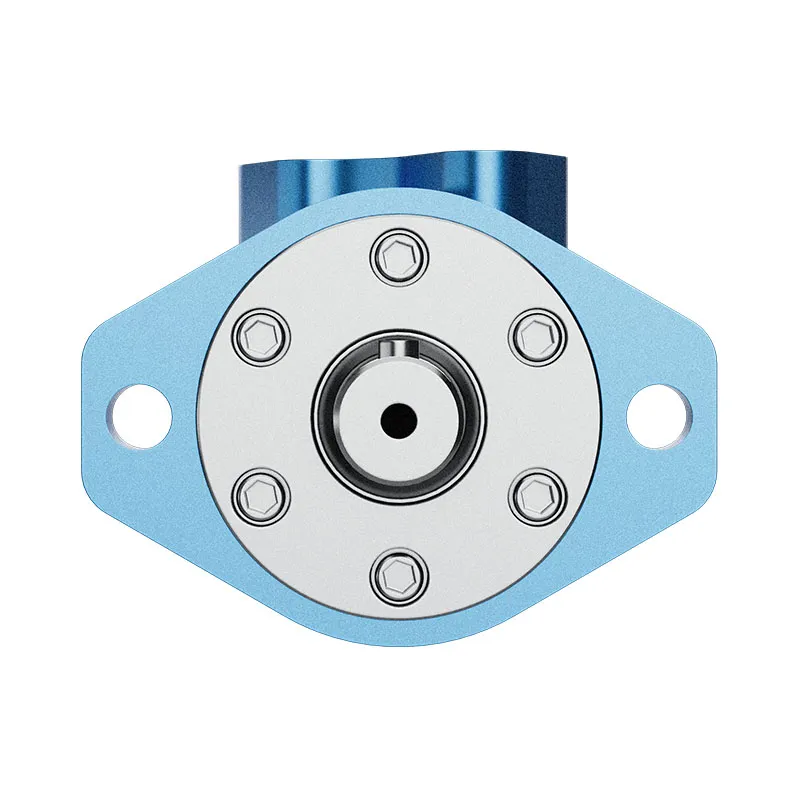
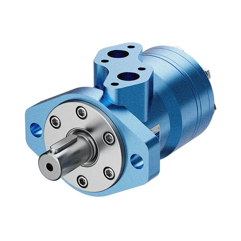
For the BMP motor range pictured in this guide, request the exact displacement, shaft, ports and duty data. The original photographs support external identification only. They do not establish low-speed smoothness, bearing capacity or suitability for a specific winding line.
Prepare a useful selection enquiry
Provide minimum and maximum working radius, line-speed range, web width and tension convention, acceleration time, roll mass or inertia, transmission details and required stopping behavior. Add the available flow, supply pressure, return pressure, fluid, temperature range and duty cycle.
Ask the supplier to evaluate the distinct high-speed and high-torque points, plus starting and low-speed behavior. Keep continuous requirements separate from brief peaks. Include a simple mechanical arrangement so that shaft and bearing loads are visible rather than buried in a torque number.
The selection is ready for acceptance when each critical operating point has a documented motor and circuit match. A displacement that works in one ideal equation is a candidate, not a completed drive design.
Foire aux questions
Does a growing roll need constant motor speed?
For constant line speed in center winding, rotational speed decreases as radius grows. Torque can increase at the same time if the required web force remains constant.
Is full web tension always the force used for a process roller?
No. For a roller between tensioned spans, the effective driving force depends on the tension difference and other loads. Identify the mechanical arrangement first.
Can a larger displacement solve every low-speed problem?
No. It changes the ideal pressure, torque and flow relationships, but stable low-speed operation and starting performance still require motor and control data.
Does motor torque capacity cover roller bearing load?
No. Radial and axial shaft loads need a separate check. A separately supported roller may be required even when the motor has adequate torque.
What is the first calculation before requesting a motor?
Convert the process force and line speed at the minimum and maximum radius into torque and speed. Those operating points provide a much clearer enquiry than a motor displacement alone.
Ressources produits et d'ingénierie associées
Moteur Orbit hydraulique à faible vitesse et à couple élevé BMP, gamme de produits de moteurs hydrauliques, Moteur hydraulique pour convoyeurs : démarrage de charge et contrôle de la vitesse, Jeu doux entre la pompe et le moteur : pourquoi le serrage d'une boulon modifie l'alignement. Confirmer le code complet du produit et les exigences d'application lors de la demande d'une revue de configuration.
Références techniques
- Cleveland State University: web-winding roller dynamics and tension
- ABB: winder radius, gearing and torque calculations
Apprentissage supplémentaire : moteurs hydrauliques
6.3 – Hydraulic Motors by NPTEL-NOC IITM provides background on motor operating principles. The lecture explains conversion of hydraulic input to shaft torque and speed, which underlies the roller-drive calculations. It supplements the component fundamentals; it is not a test procedure for the complete circuit discussed above.