Wenzhou Prance Hydraulic Equipment Co., Ltd

Hydraulic Motor Speed Droop Under Load: Leakage or Insufficient Flow?
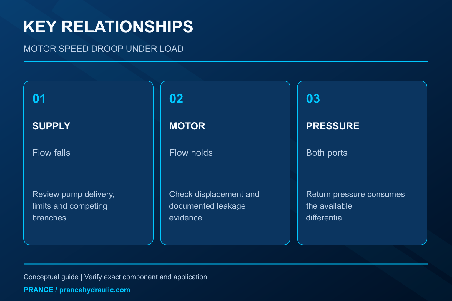
Hydraulic motor speed droop under load can come from increased internal leakage, reduced flow reaching the motor, or both. A constant pump command does not prove constant motor inlet flow. Before condemning the motor, compare actual shaft speed, delivered inlet flow, differential pressure, temperature, and the state of competing branches. When displacement is fixed and inlet flow truly remains constant, a larger leakage share leaves less flow available to produce rotation. When inlet flow falls, investigate the supply and control circuit as well as the motor.
This guide addresses a motor that runs but slows as resisting load rises. It separates that condition from initial breakaway torque, low-speed stick-slip, and uncontrolled overrunning loads, which require their own analysis.
Start with a matched comparison
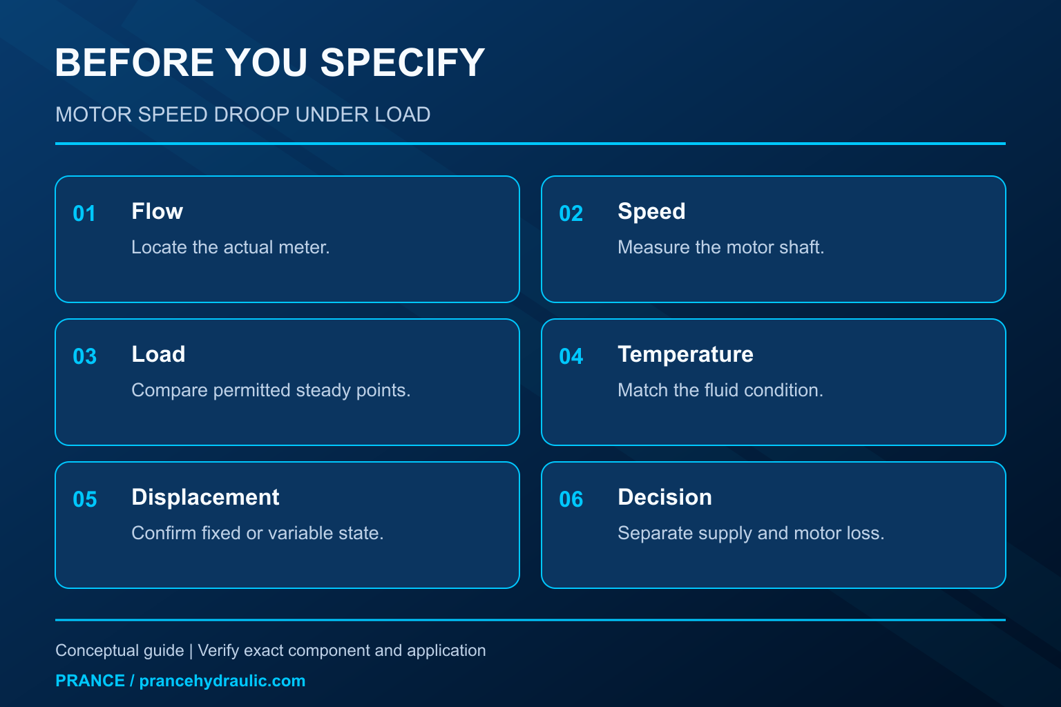
Choose two stable operating points that the machine is permitted to reach: a lighter load and a higher resisting load. Keep the same direction, commanded operating mode, motor displacement, and reasonably matched fluid temperature. Record actual shaft speed and pressure at both motor ports. A single inlet gauge does not establish the pressure difference across the motor.
Use a suitable flow measurement at a defined location. Flow leaving the pump can split among a motor branch, relief path, priority function, and pilot circuit. A pump-outlet meter therefore may not establish the amount entering the motor. Identify the meter’s position on the actual schematic, including every branch between it and the motor.
Perform instrument installation only after safe isolation and verified pressure release. Do not stall a motor, close a drain, defeat a brake, or suspend a load to create a convenient test point. Where a safe load comparison is unavailable, preserve the existing observations and use the machine manufacturer’s diagnostic procedure.
Relate speed to the flow that produces displacement
For an ideal fixed-displacement motor, speed in revolutions per minute equals 1,000 times displacement flow in litres per minute divided by displacement in cubic centimetres per revolution. Real inlet flow also supplies internal leakage and any design-specific contributions included in the chosen boundary. The flow that actually produces shaft rotation is consequently smaller than total inlet flow in normal motoring operation.
An alternative expression uses inlet flow multiplied by volumetric efficiency. The efficiency must belong to the actual operating point; a single catalog figure cannot be assumed across every pressure, speed, and temperature. The HAWE fluid lexicon describes the general speed characteristic and the role of leakage. Its numerical examples for particular constructions are not limits for Prance motors.
This relation explains a diagnostic distinction. If inlet flow remains unchanged while speed falls, the useful displacement-flow share has decreased or effective displacement has changed. If inlet flow decreases at the same time, the supply is part of the explanation. Neither observation alone establishes which component must be replaced.
Use a hypothetical example without turning it into a wear limit
Suppose a fixed-displacement motor has a hypothetical displacement of 100 cm³/rev and receives 20 L/min. If 1 L/min does not contribute to rotation within the defined boundary, 19 L/min corresponds to 190 rpm. If that non-driving share increases to 3 L/min while inlet flow remains 20 L/min, the corresponding speed is 170 rpm.
Now consider a different observation: inlet flow falls to 18 L/min and the non-driving share remains 1 L/min. That also produces 170 rpm. The same shaft speed can therefore arise from a motor-side flow change or a supply-side shortage. Measuring speed alone cannot distinguish them.
These inputs are calculation examples, not normal leakage, acceptable speed droop, or ratings for the Prance BMS series. Real diagnosis requires known displacement, a defined flow boundary, and the motor’s documentation. A changing-displacement motor also requires its actual displacement state; applying a fixed-displacement calculation during a shift can falsely suggest leakage.
Compare the evidence in a practical order
| Observation at matched conditions | What it suggests | Next distinction |
|---|---|---|
| Speed falls and measured motor inlet flow falls | Supply or branch flow is changing | Compare pump output, other consumers, and control state |
| Speed falls while motor inlet flow stays similar | More flow is not producing rotation, or displacement changed | Confirm displacement and approved leakage measurements |
| Pump output stays similar but motor branch flow falls | Flow is being diverted before the motor | Review relief, priority, bypass, and valve paths |
| Return pressure rises with load or another function | Available motor pressure difference may be constrained | Measure both ports and inspect approved return routing |
| Speed drops only during rapid load changes | Transient supply, control, or inertia effects | Separate the transient from the settled operating point |
The table is a qualitative decision aid. It provides no universal rejection threshold. Follow the exact motor and machine methods before opening drain connections or changing valve settings. Some motors route leakage internally, and an external case-drain measurement may not be available or may include additional flow.
When the pump or prime mover causes the droop
A pump can maintain a nominal command while delivering less flow at higher pressure. Its internal losses may increase, its pressure control may destroke it, or a power-limiting function may intentionally reduce displacement. The electric drive or engine may also slow under load. Actual pump speed matters more than a fixed command percentage.
Check whether the operating point approaches a documented pressure or power boundary. If motor speed falls as the pump enters pressure compensation, the motor may simply be receiving less oil. Raising the pressure setting without understanding the load and component limits can create a much more serious problem than the original speed reduction.
In a shared supply, another function can consume part of the flow or a priority valve can allocate it elsewhere. Compare motor branch flow with pump flow during the same event. If the difference grows, investigate the intervening circuit. Do not increase pump displacement simply to hide a leaking relief path or a control valve that is not reaching the intended position.
When motor losses deserve investigation
A motor-side investigation becomes more persuasive when actual inlet flow, displacement, temperature, and pressure conditions are known. Increasing pressure difference often changes internal leakage, so an unloaded comparison cannot be treated as a loaded acceptance test. Use a documented baseline at comparable conditions where one exists.
Drain-flow measurements require particular care. The observed return can include intentional flushing or control flow, and some internal leakage can return by a route that the meter does not capture. A larger external drain reading is therefore supporting evidence, not a complete volumetric-efficiency calculation unless the manufacturer’s method says it is.
Correlate the hydraulic observations with temperature, abnormal noise, fluid condition, and service history. A sudden change after a hose replacement or valve adjustment calls for routing and setting checks before an assumption of gradual wear. A worsening trend under consistently matched conditions deserves escalation, but diagnosis still must identify the actual failure mechanism before specifying repair.
Back pressure can consume the torque margin
Motor torque is associated with the pressure difference across the working ports, subject to mechanical losses. Inlet pressure alone can look adequate while a restricted return consumes part of that difference. The load may then push the system into a pressure limit, causing reduced flow and speed.
Measure the return at an appropriate approved point. Long hoses, fittings, filters, coolers, and simultaneous return flow can influence it. Their effect depends on the actual routing and fluid condition. Never remove a return restriction by bypassing required filtration or cooling without an engineered and approved procedure.
Case pressure is a separate limit. It should not be substituted for outlet-port pressure in a torque calculation, and an outlet-port reading does not prove the case is safely drained. Confirm the motor’s actual construction and drain requirements. Similar external dimensions do not establish identical internal return arrangements.
Separate steady droop from a transient
A motor can briefly slow when load rises because the circuit and rotating assembly need time to reach a new condition. Pump controls, valve response, compressibility, and inertia can all affect the transition. That brief event should not be confused with a permanently lower settled speed.
Capture synchronized readings if the instruments support them. A pressure trace from one run and a flow reading from another can create an apparent relationship that never occurred. If only slow instruments are available, restrict the conclusion to stable points and explicitly leave the transient unresolved.
Closed-loop speed control may compensate for a disturbance by demanding more flow. If the correction reaches a command or supply limit, speed will still fall. Review the actual limit and available authority rather than assuming that a higher controller gain can create missing hydraulic capacity. Controller changes require the machine’s approved commissioning process.
Turn the result into a useful repair or purchasing request
For a Prance BMS gerotor orbit motor inquiry, provide the complete ordered code and displacement rather than only the series name. Include required loaded speed, torque or load description, actual flow, both port pressures, fluid temperature, and the operating direction. Ask the supplier to confirm the permitted operating envelope for that exact configuration.
If evidence points upstream, report that clearly. A new motor will not restore flow diverted through a bypass or lost when a pump reaches its power limit. If evidence points toward motor losses, request the approved test method and acceptance conditions. Avoid asking for an unsupported universal leakage number.
After a correction, repeat the same matched operating comparison with the same boundaries. Verify required speed, stable control, safe pressures and temperature, and absence of unintended motion. Preserve the measurements as a future baseline. A successful no-load run alone does not demonstrate that the original loaded-speed problem has been resolved.
FAQ
Can constant pump command prove constant motor flow?
No. Pump speed, pressure compensation, power limits, leakage, and other branches can change delivery. Measure the actual motor branch flow or follow a documented method that establishes it.
Does high inlet pressure prove enough motor torque is available?
No. Working torque depends on the pressure difference between the ports and on losses. Elevated return pressure can reduce that difference even when the inlet gauge looks high.
Is a speed drop always evidence of a worn motor?
No. Reduced supply, bypass flow, changed displacement, a pressure limit, or control behavior can produce the same symptom. Use simultaneous flow and pressure evidence before assigning the cause.
Can a larger motor fix loaded speed droop?
Not automatically. Increasing displacement requires more flow for the same speed. It may help torque capability while making a supply-flow shortage more visible, so evaluate the complete operating point.
Why repeat measurements after the oil reaches a stable temperature?
Temperature changes viscosity and can alter leakage and pressure loss. Matched, stabilized conditions make comparisons meaningful; unmatched cold and hot readings cannot establish a reliable wear trend.
Product and related engineering resources
The Hydraulic Gerotor Orbit Motor BMS is the relevant product category for this guide. The illustrations explain concepts and do not depict the product internals or establish operating limits. Confirm the complete code and approved documentation. Related resources: Moteur orbital hydraulique à gérotor BMS, hydraulic motor range, Hydraulic Motor Speed Calculation From Flow and Displacement, Hydraulic Motors in Series vs Parallel: Flow, Speed, and Load Sharing.
Sources and limits of this guide
General engineering principles are separated from product facts. Numerical examples are hypothetical, not Prance ratings. Proprietary client writing templates and parameter-table originals were not supplied.
- NPTEL: Fundamentals of Industrial Oil Hydraulics and Pneumatics
- NIOSH: preventing injuries from hazardous energy
- HAWE fluid lexicon: speed characteristic of hydraulic motors; general relation only
University lesson: operating principles
NPTEL-NOC IITM presents 6.3 – Hydraulic Motors. The lesson supports the motor flow, displacement and torque used in this discussion; it is not a model-specific performance or installation approval.