Wenzhou Prance Hydraulic Equipment Co., Ltd

Orbit Motor Valve Timing: Gerotor Commutation Explained
Orbit motor valve timing is the relationship between the distributor's oil passages and the changing working chambers in the gear set. Correct timing connects expanding chambers to the appropriate supply path and contracting chambers to the outlet path. The required relationship depends on the exact motor design and assembly instructions. Do not use universal timing marks, tooth positions or a procedure from a visually similar motor.
This guide explains the mechanism and the evidence needed when an orbital motor runs poorly after service. It is not a teardown recipe. Internal timing, matched parts and assembly positions must be established from the selected motor's controlled service information.
Understand the chamber sequence
An orbital motor's internal gear arrangement creates chambers whose volumes change as the mechanism moves. The distributor connects those chambers to the working ports in a coordinated sequence. That coordination is what makes pressure produce useful shaft torque rather than simply circulate or oppose the intended movement.
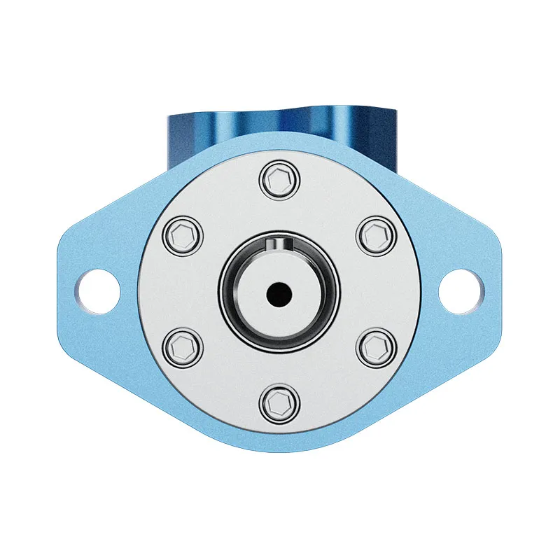
The gear set and output motion are not described adequately by a photograph of the outer housing. The internal motion and distributor relationship matter. A repair that preserves the exterior connections can still change the internal sequence if parts are assembled incorrectly. Establish the exact motor configuration before reviewing a timing-related symptom.
Distinguish the distributor design
Orbital motors can use different distributor arrangements, including designs where valve function is associated with the output shaft and designs with a separate disc and drive arrangement. The method of coordinating motion and oil passages differs accordingly. A service instruction for one arrangement should not be transferred to another.
Record the full code, relevant parts list and drawing revision. If the motor has been rebuilt with substituted components, establish what is actually installed. The same family name may not identify every internal revision. A supplier's general cutaway is useful educational context but does not replace the assembly information for the specific unit.
Separate timing from port-based rotation direction
Changing which work port receives flow can reverse a suitable bidirectional motor, but that is not the same as changing internal valve timing. Rotation should be verified using the selected motor's port drawing and viewing convention. Incorrect external connections and incorrect internal assembly can produce different faults.
Do not rotate internal parts arbitrarily to correct a machine that simply has reversed commands or hoses. First identify the intended external direction and verify the circuit. Opening a correctly assembled motor can introduce contamination, damage seals and remove evidence without addressing the actual connection problem.
Recognize timing-related symptoms cautiously
Poor starting, irregular rotation, abnormal pressure behavior or unusual heating after overhaul can justify checking the assembly record. These symptoms are not unique to timing. Low inlet flow, brake drag, excessive load, distributor wear and other circuit problems can look similar. Compare the symptom with the maintenance timeline and measured operating conditions.
If the problem began immediately after dismantling, review the exact procedure and part identity before repeated loaded tests. A suspected internal assembly fault should not be investigated by forcing the motor against a high load. Preserve the repaired configuration and have it assessed through the appropriate service process.
Preserve orientation during an approved repair
When qualified service personnel dismantle a motor using the correct procedure, retain part orientation, matched sets and identification. Photograph the sequence and keep parts protected. Marking should not damage sealing, bearing or valve surfaces. Do not clean away useful observations before the inspection is documented.
If orientation has already been lost, obtain the controlled assembly information rather than guessing from old paint marks or another motor. Marks left by a previous repair may not be factory timing references. Distinguish manufacturer instructions from informal workshop practices and record the source of the assembly decision.
Check parts and revisions before adjusting position
A motor may contain a gear set, distributor, drive link and plates intended to work as a defined combination. An incorrect or mismatched replacement can affect operation even when its dimensions appear close. Compare part numbers, revision notes and the permitted service substitutions.
Do not assume that changing an angular position will make an incompatible component set correct. Ask the repair provider which parts were reused, replaced or matched and what inspection limits were applied. A meaningful service report connects the component identity with the approved assembly method rather than stating only that timing was checked.
Use an investigation table
| Evidence or symptom | Question to resolve | Useful next action |
|---|---|---|
| Fault appeared after overhaul | Was the exact service procedure followed? | Review the assembly record and controlled instructions |
| Wrong direction on the machine | Are external commands and work ports correct? | Verify port map and shaft-view convention first |
| Irregular low-speed motion | Is the issue hydraulic, mechanical or internal? | Record speed, both work pressures and load state |
| Parts were substituted | Are revisions and matched components compatible? | Compare part identity with approved service information |
| Orientation was lost | Are valid timing references available? | Obtain the exact assembly method rather than guessing |
| Heat or pressure changed | Does an external restriction or brake explain it? | Check circuit and brake conditions before attributing timing |
The table organizes evidence. It does not establish a timing correction or approve continued operation of a motor suspected of incorrect assembly.
Inspect valve surfaces with the correct criteria
Distributor wear, scoring, contamination or distortion can affect sealing and flow distribution. Correct angular assembly does not make a damaged surface serviceable. Inspection should cover the applicable dimensions, surface condition and mating arrangement under the motor's service criteria.
Avoid polishing or lapping parts without an approved procedure. Removing material can change clearances and sealing behavior, even if the surface appears smoother afterward. A repair provider should identify the measured findings and permitted corrective action. Keep observations separate from an unsupported conclusion that every mark requires replacement.
Exclude flow and load problems before teardown
Measure the actual flow reaching the motor and both work-port pressures under a safe controlled condition. Check that the valve is supplying the intended path and that a relief or bypass is not diverting flow. A low-speed command may deliver less flow than assumed, especially when another machine function operates simultaneously.
Review brake release, coupling alignment and external loading. A dragging brake can cause poor starting and high pressure after a motor replacement, creating the impression that the internal timing is wrong. Establish the complete operating state before choosing an invasive repair. If testing cannot be performed safely, document the limitation and use an appropriate bench assessment.
Use an approved bench test after repair
A repaired motor should be tested through a defined procedure with the actual configuration identified. Record flow, pressure difference, speed, output performance, temperature and any relevant drain conditions. Check both directions if the selected design and application are bidirectional. State what the test demonstrates and which conditions were not covered.
Do not use a free spin at negligible load as proof of correct full-duty performance. The test needs relevant operating points and acceptance criteria. If abnormal behavior appears, stop and investigate rather than changing several internal positions until the motor seems to run. An untraceable trial-and-error assembly cannot support a reliable repair claim.
Compare starting and running behavior separately
A motor can rotate at higher speed yet start poorly or move unevenly at low speed. Starting torque, friction and flow distribution are not fully described by a single steady efficiency figure. Review the selected motor's starting and low-speed requirements and test them using the approved method.
Record the load and oil temperature for each observation. If the application requires smooth indexing or slow controlled movement, define that requirement in the repair acceptance plan. A generic test at a different speed may miss the condition that matters to the machine even when ordinary running measurements look acceptable.
Decide whether repair evidence is sufficient
Accept a repair only when the configuration, inspection findings, assembly procedure and test results are documented to the agreed scope. If essential timing information or parts identity cannot be established, do not claim a verified internal repair. Consider a qualified service provider or a replacement motor with a complete application comparison.
Replacement still requires the mechanical, hydraulic and control checks. A new unit does not correct an external valve or load problem. Preserve the original failure record and any removed components so the decision remains traceable and the same cause is not overlooked after installation.
Information needed for a service enquiry
Provide the full motor code, serial or revision details, hydraulic circuit and the symptom timeline. State whether the motor was opened, which parts changed and whether assembly orientation was preserved. Include safe-test readings of flow, speed, pressures and temperature and photographs of identified internal parts if already dismantled.
Ask for the exact service procedure, approved part combination and post-repair acceptance method. Request a distinction between timing, wear and external circuit explanations. The useful response is a documented assessment and procedure, not a universal instruction to shift a gear by one tooth.
Perguntas frequentes
Are there universal timing marks for orbital motors?
No. Timing and assembly references depend on the exact design and revision. Use its controlled service information rather than marks or procedures from another motor.
Can reversing the hoses fix internal timing?
It changes external flow direction on a suitable motor; it does not establish correct internal assembly. Verify the circuit and rotation convention before considering teardown.
Does uneven rotation prove incorrect timing?
No. Flow, load control, brake drag, friction, wear and other conditions can create similar behavior. Use the maintenance history and measured state to separate causes.
Is a no-load spin enough after overhaul?
No. Use a defined test with relevant pressure, flow, speed, direction and acceptance conditions. Starting and low-speed behavior may need separate checks.
What if part orientation was lost?
Obtain the exact assembly procedure and verify the component set. Do not guess from a similar motor or repeatedly alter positions under loaded operation.
Produtos e recursos de engenharia relacionados
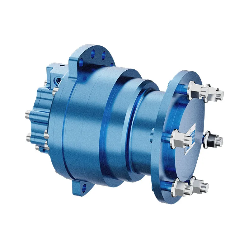
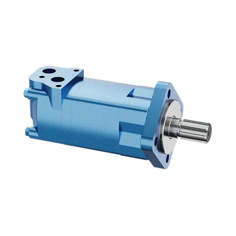
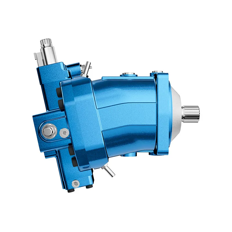
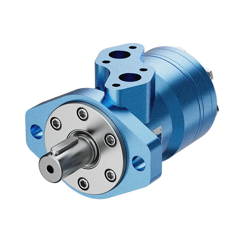
Para uma consulta sobre um componente, consulte Motor Orbital Hidráulico de Baixa Rotação e Binário Elevado BMP e forneça a especificação completa e as condições de instalação. Guia relacionado: Área de atuação do motor de pistão, Faixa de alcance do motor orbital, Verificações de pressão no motor, Medição de vazão de drenagem do motor, Calculo da eficiência do motor, Orbit Motor Internal Leakage: Wear Points and Diagnostic Tests, Direção de rotação do motor hidráulico: Conexões de entrada e saída e reversão. As fotografias dos produtos ilustram as configurações do catálogo; elas não estabelecem a classificação de pressão, velocidade ou carga axial para um pedido não confirmado.
Conferência universitária: fundamentos do motor hidráulico
O NPTEL-NOC da IITM apresenta uma aula sobre motor hidráulico do IIT Madras. A apresentação apoia a distinção entre a entrada hidráulica e a saída do eixo, conforme descrito neste guia. As limitações de instalação e operação específicas dos componentes ainda exigem a documentação do motor selecionado.
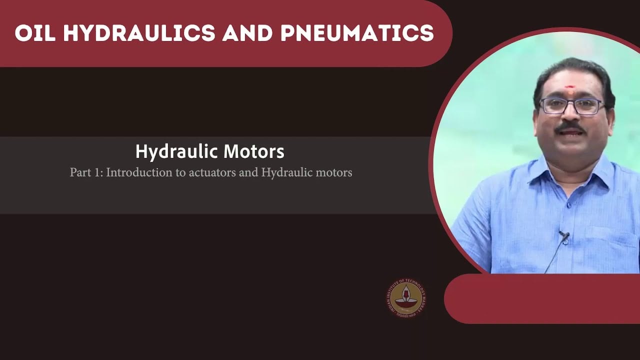
Aprenda mais sobre os motores hidráulicos no NPTEL.
Referências técnicas e de segurança
- NPTEL: Fundamentos de Hidráulica e Pneumática Industrial
- NIOSH: prevenção de lesões causadas por energia perigosa
- Referências técnicas: princípios de funcionamento e instalação de motores orbitais
Essas referências fornecem contexto educacional e técnico. As classificações específicas de um modelo de fabricante não constituem especificações para um produto da Prance e não implicam filiação ou autorização à marca.