Wenzhou Prance Hydraulic Equipment Co., Ltd

Proportional Hydraulic Valve Deadband: Measurement and Compensation
What proportional hydraulic valve deadband means
Proportional hydraulic valve deadband is the input region around an operating point where a change in command produces no significant change in the selected output under defined conditions. For a directional spool valve, overlapping metering edges can create a central region before a useful flow path opens. Electronic settings, friction and the measurement threshold can add other apparent inactive regions. Measure the exact command-to-output relationship before adding compensation. A motor that does not start immediately is not proof of valve deadband: load friction, insufficient pressure and the control sequence can produce a similar symptom. A useful diagnosis separates those effects rather than turning up gain until the machine moves.
The chosen output matters. A position-feedback signal describes spool position, while a flow instrument describes delivered fluid. An actuator-position signal includes the valve, circuit and mechanical load. Keep these measurements distinct. A valve can show spool movement before measurable flow appears, and measurable flow can exist before a loaded actuator begins moving.
Distinguish deadband from neighboring problems
Deadband, hysteresis and stiction describe different observations. Deadband is an inactive input interval according to a stated output criterion. Hysteresis is a difference in output or transition point depending on the direction of approach. Stiction is resistance to the beginning of motion after rest. They can occur together, but one remedy does not automatically correct all three.
For example, slowly increasing a command from neutral might produce a transition at one value. Returning toward neutral might cross the selected flow threshold at another. The difference is evidence of approach-dependent behavior under those conditions, not an instruction to assign the whole difference to geometric overlap. Repeat the test and record pressure, temperature and settings before interpreting the result.
Mechanical load friction introduces another boundary. If flow begins while the cylinder remains stationary, the actuator can be waiting for the pressure needed to overcome resistance. Compensation derived only from the first visible movement may overestimate the valve's own inactive range. This matters especially when a machine later operates with a lighter load or a warmer circuit.
Identify the complete valve and control chain
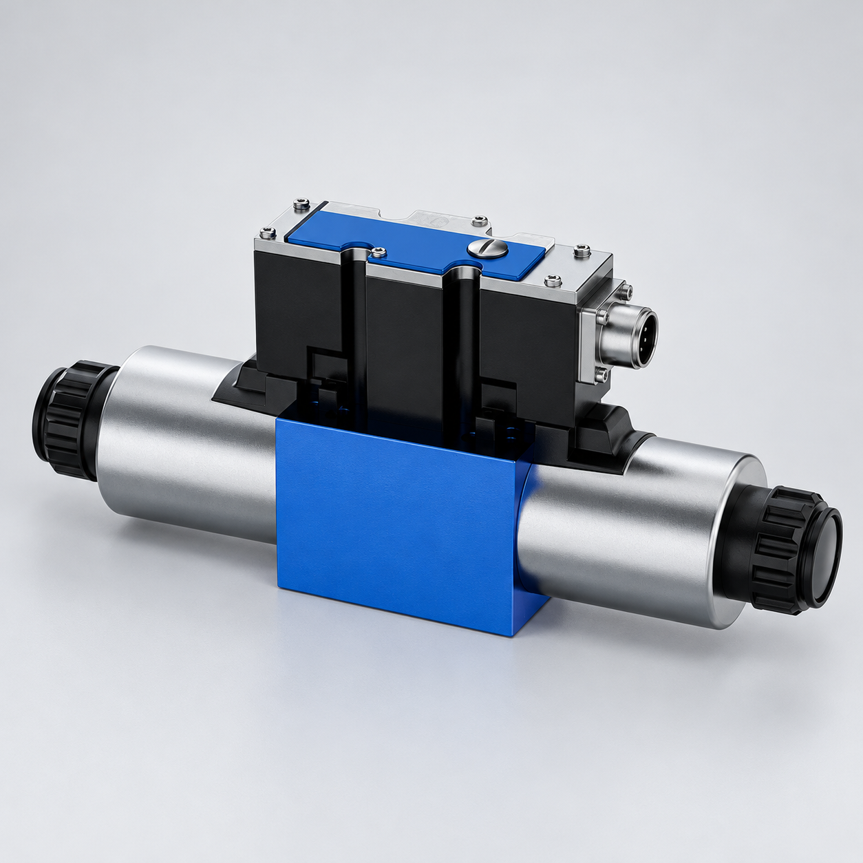
Record the valve order code, spool symbol and electronic driver identity. Note whether the valve has integrated electronics or uses a separate amplifier. State the command interface and the meaning of its neutral value. A signed analog command, a digital setpoint and a pulse-width-modulated coil drive are different signals, even if the operator sees the same percentage display.
Record enabled functions such as command ramps, current limits, minimum-current settings, offset, dither and internal feedback. The control chain may deliberately suppress small commands or apply a calibrated minimum drive. A trace recorded at the controller's output cannot prove that the same waveform reaches the coil or the integrated electronics.
Review documentation before changing any setting. A feedback-controlled valve may not expose the same adjustments as an open-loop proportional solenoid valve. A control labeled offset may serve an electronic calibration function rather than a mechanical spool adjustment. Do not copy another model's instructions just because two products have similar housings.
Design a controlled measurement
Use a guarded test arrangement that prevents uncontrolled actuator movement. Define supply and load pressures, tested flow path, fluid and measured temperature. State the output instrument, measurement threshold and acquisition method. Keep the circuit inside the valve's approved limits. A test should reveal behavior without placing personnel near a moving or pressurized system.
Start from a documented operating state. Sweep the command gradually across the region of interest, then reverse the sweep. Use a rate that is appropriate to the intended static measurement and instrument response. An excessively rapid sweep includes dynamic lag, while a very slow sweep can expose additional effects from rest and friction. Record the rate instead of calling every sweep a universal deadband test.
Repeat both positive and negative directions. Directional valves and connected loads need not behave identically in both directions. Retain raw command, pressure and output data, together with timestamps. If a spool-position signal is available, use it only through the approved interface and with its calibration understood.
| Observação | What to investigate | Why automatic compensation may be wrong |
|---|---|---|
| Command changes but the driver input does not | Controller scaling, interlocks, communication and signal wiring | A software or signal-path delay is not valve geometry |
| Driver input changes but coil current remains unchanged | Driver dead zone, minimum-current settings and current limits | Additional offset can conceal an incorrectly configured driver |
| Spool position changes before measurable flow | Metering-edge overlap and the flow threshold | Movement-based calibration differs from flow-based calibration |
| Flow begins before the actuator moves | Load friction, pressure buildup and mechanical condition | Actuator movement can exaggerate the apparent valve inactive range |
| Threshold changes between increasing and decreasing sweeps | Hysteresis, friction, temperature and test repeatability | A single threshold cannot describe both approach directions |
| Neutral flow grows after an offset change | Compensation magnitude and neutral configuration | Improved startup can create unwanted creep or heating |
For the control principles behind these distinctions, see NPTEL servo and proportional valve teaching. This decision table is not a product specification.
The table describes diagnostic distinctions, not guaranteed results for a particular model. University proportional-control teaching supplies the general concepts; use the exact valve and driver instructions to decide which measurement and adjustment is permitted.
State how the result is calculated
Define the inactive interval using measured thresholds. For an illustrative signed command, suppose the chosen flow threshold is first crossed at positive 6 percent and negative 4 percent of command span. Under that test convention, the interval extends from minus 4 to plus 6 percent. Those example values explain reporting; they are not a Prance specification or a recommended compensation setting.
Include the threshold's units and the conditions used to find it. A threshold based on noise-floor separation differs from a threshold based on useful application flow. If flow is normalized to a reference value, identify that reference. If data are filtered, retain the filter settings and explain whether the filtering changes the transition location.
Report individual direction results and repeatability. Averaging asymmetric values into one convenient number can hide an important difference. Distinguish rising-command and falling-command observations rather than presenting one line as the entire valve characteristic. If the data do not clearly separate signal noise from output, report the limitation instead of declaring an exact boundary.
Apply compensation only to the identified cause
A controller can map a small nonzero command to a drive that overcomes a characterized inactive region. This may improve low-speed behavior in an appropriate design, but it changes the relationship between operator demand and valve drive. The transition from neutral must remain controlled, predictable and compatible with the machine's safety functions.
Do not add an offset indiscriminately at zero command. An unintended drive can open a flow path and create actuator creep. A machine's neutral condition may depend on both valve configuration and other circuit elements. Before adjusting minimum drive, document how the system maintains a safe stationary state and how the modified mapping behaves during faults or disabled operation.
Separate compensation from gain. Gain changes the slope of the input-output relation outside the inactive region. Offset changes its position or initial drive. Altering both together makes diagnosis difficult and can cause abrupt movement when the threshold is crossed. Preserve the original configuration and change only the approved parameter needed for the tested purpose.
Account for temperature and direction
A compensation setting that works during one bench condition may not give the same response after a cold start or under a different load. Fluid behavior, pressure forces, solenoid temperature and friction can affect the observed relation. Verify the proposed mapping over the application's permitted conditions rather than assuming one warm, unloaded sweep is sufficient.
If the control architecture supports separate directional compensation, justify it from measured data and the manufacturer's guidance. Do not use asymmetry to conceal damaged components, incorrect wiring or an unsuitable spool. First establish that the assembly and signal polarity match the intended circuit.
Repeatability matters as much as one successful startup. If the threshold varies widely, a fixed compensation can alternate between insufficient response and excessive motion. Investigate contamination, mechanical condition, driver behavior and measurement stability before making a more aggressive mapping.
Understand what dither can and cannot do
Dither is a deliberately applied oscillatory drive used in suitable proportional-control arrangements to influence friction-related behavior. Its frequency and amplitude must match the valve, driver and application. It is not a substitute for correcting an incorrect signal interface or repairing contamination-related damage.
Dither does not universally remove geometric spool overlap. It may change the measured response around a threshold, and excessive or unsuitable settings can create pressure or motion ripple. Keep the approved settings recorded during every deadband test. Comparing a valve with dither enabled against another with it disabled does not isolate the effect of the valve mechanism.
For integrated electronics, consult the complete product documentation before adding an external modulation signal. The internal control may already apply the necessary drive treatment. An additional signal can interfere with that control rather than improve it. Do not infer the permitted settings from a photograph or a generic tutorial.
Include deadband in an RFQ and acceptance plan
Ask the supplier to define the measured output, command range, pressure and flow conditions, fluid temperature, driver settings and threshold convention. Request traces in both directions with repeated observations. A quoted deadband percentage without those details is difficult to compare against another supplier's figure.
Explain the application's need: minimum controllable speed, neutral holding behavior, acceptable startup motion and operating range. Discuss the complete circuit, including feedback and load conditions. An exceptionally small bench deadband does not by itself guarantee satisfactory positioning or safe load holding in the machine.
Keep acceptance criteria tied to a verified configuration. If electronics or a spool option changes, confirm whether the previous calibration and test remain valid. Store the approved parameter file, test report and valve identity together so a later replacement can be evaluated using the same definitions.
Perguntas frequentes
Does every proportional valve have the same deadband?
No. Spool geometry, control architecture, configuration and test definitions differ. Compare documented measurements of the relevant configurations under comparable conditions, rather than using one generic percentage.
Can cylinder startup identify valve deadband directly?
It can identify a system startup threshold, but the result includes pressure buildup and load friction. Use flow or approved spool-position measurements when the purpose is to separate the valve's behavior from the actuator's behavior.
Is deadband compensation a way to hold a load safely?
No. Load holding requires an appropriate circuit and components for the duty. Compensation changes command behavior and must not be treated as a substitute for a verified holding or stopping function.
Should I increase dither until the deadband disappears?
No. Use the permitted valve and driver settings, and monitor ripple and stability. Dither addresses particular friction-related effects and does not universally eliminate metering-edge overlap or other circuit limitations.
What should I preserve before making an adjustment?
Preserve the complete valve identity, original parameter file, circuit arrangement and baseline traces. Record every approved change and repeat the relevant neutral, startup and operating-condition checks before accepting it.
Related products and engineering guides
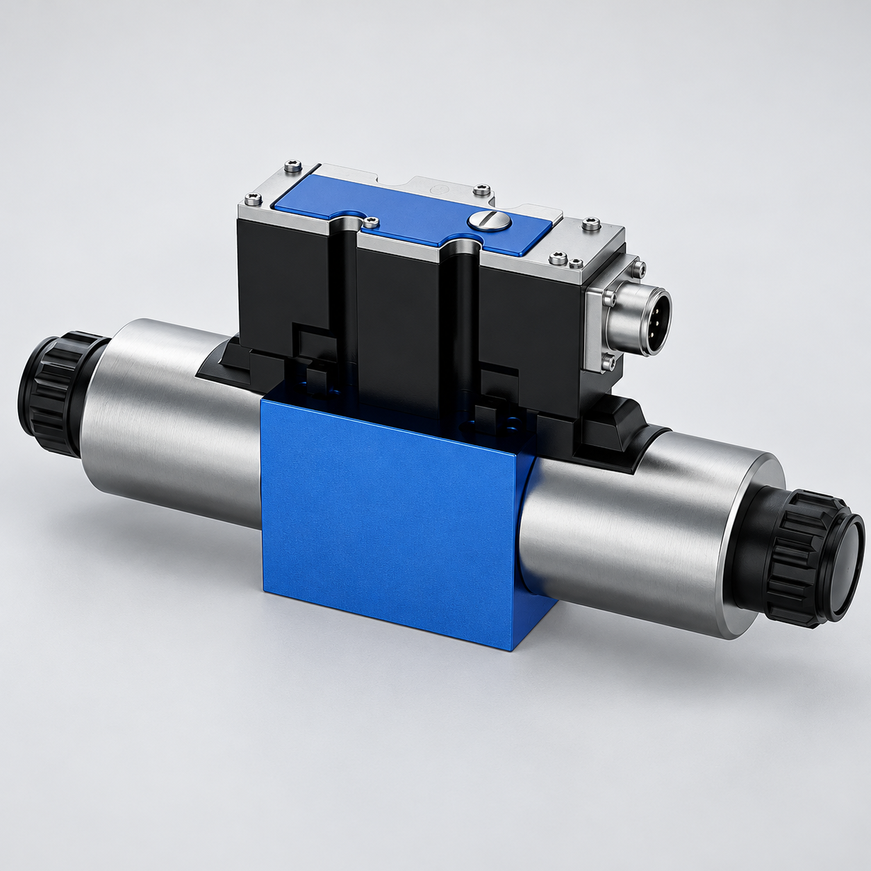
For a duty-based enquiry, review 4WRAE proportional valve. Confirm the complete ordered configuration, drawings, operating conditions and integration responsibilities with the supplier. Related resources: hydraulic valve range, solenoid valve principles, voltage-drop diagnosis, internal leakage diagnosis.
University lesson: proportional and servo valve principles
This NPTEL IIT Kharagpur university lecture explains the general construction and operating principles of proportional and servo valves. Model-specific settings and adjustment permissions still require exact component documentation.

Technical references
- NPTEL: servo and proportional control principles
- NPTEL: proportional solenoids, feedback and dither
- NIOSH: hazardous-energy isolation
These sources provide technical, educational and safety context. Example calculations are illustrative, and neither their inputs nor another manufacturer’s component data establish a Prance product rating or brand affiliation.