Wenzhou Prance Hydraulic Equipment Co., Ltd

Hydraulic Oil Cleanliness Codes: ISO 4406 Targets by Component
The hydraulic oil cleanliness code ISO 4406 reports solid-particle contamination as three scale numbers. In the usual automatic-particle-count format, those numbers describe cumulative counts at the specified 4, 6 and 14 micrometre calibrated size thresholds. Lower numbers indicate cleaner fluid, but the code alone does not tell a buyer which target is suitable for an unidentified pump or valve. Select a target from the actual component requirements and verify it at a representative sampling point. This guide explains how to interpret reports, compare trends, and build a practical cleanliness specification without inventing universal acceptance limits.
Understand what the three numbers describe
ISO 4406 is a coding method for the level of contamination by solid particles. It is not a complete fluid-health certificate and does not itself establish the allowable contamination for every hydraulic component. The usual three-number result comes from counting particles at or above three stated size thresholds, rather than separating the sample into three non-overlapping size bands.
For example, a reported particle in the largest threshold also contributes to the counts at the smaller thresholds. Do not add the three cumulative counts to estimate a total number of independent particles. Keep the measured counts, their units and the coded result together when the laboratory supplies them.
The micrometre notation with a calibration suffix matters. Do not compare a modern calibrated automatic count with an older report merely because both use a slash-separated code. Ask the laboratory which method, calibration and standard edition it used. Record those details before creating a baseline or declaring a historical change.
Read changes without treating the code as linear
The scale represents particle-count ranges. A movement of one scale number corresponds approximately to a factor-of-two change in the relevant count range. It is not a one-percent improvement or a one-particle difference. Two samples inside the same range can have the same code while their exact counts differ appreciably.
Use the actual counts when investigating a trend close to an acceptance boundary. A single slash-separated result can hide the difference between a stable condition and a rising population that has not yet crossed the next code boundary. Keep repeatability and sampling variation in view rather than treating the scale as infinitely precise.
Also compare corresponding thresholds. A change in the smallest-particle code may have a different diagnostic implication from a sharp rise at the largest threshold. It still does not identify particle composition or prove the origin of wear. Interpretation needs operating history, sample quality and any supporting analysis.
Obtain component-specific targets before choosing a limit
Start with the selected pump, motor, valve and other sensitive devices. Request the manufacturer's documented cleanliness requirement for the exact configuration, fluid and operating duty. Ask whether it is a normal operating requirement, an installation requirement or a condition attached to a particular life expectation or service recommendation.
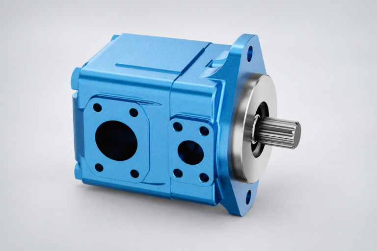
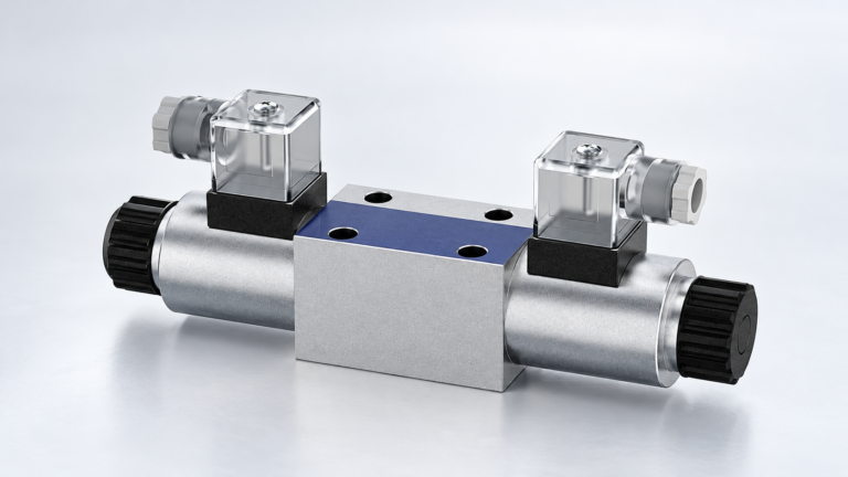
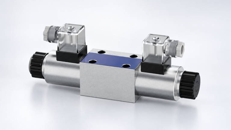
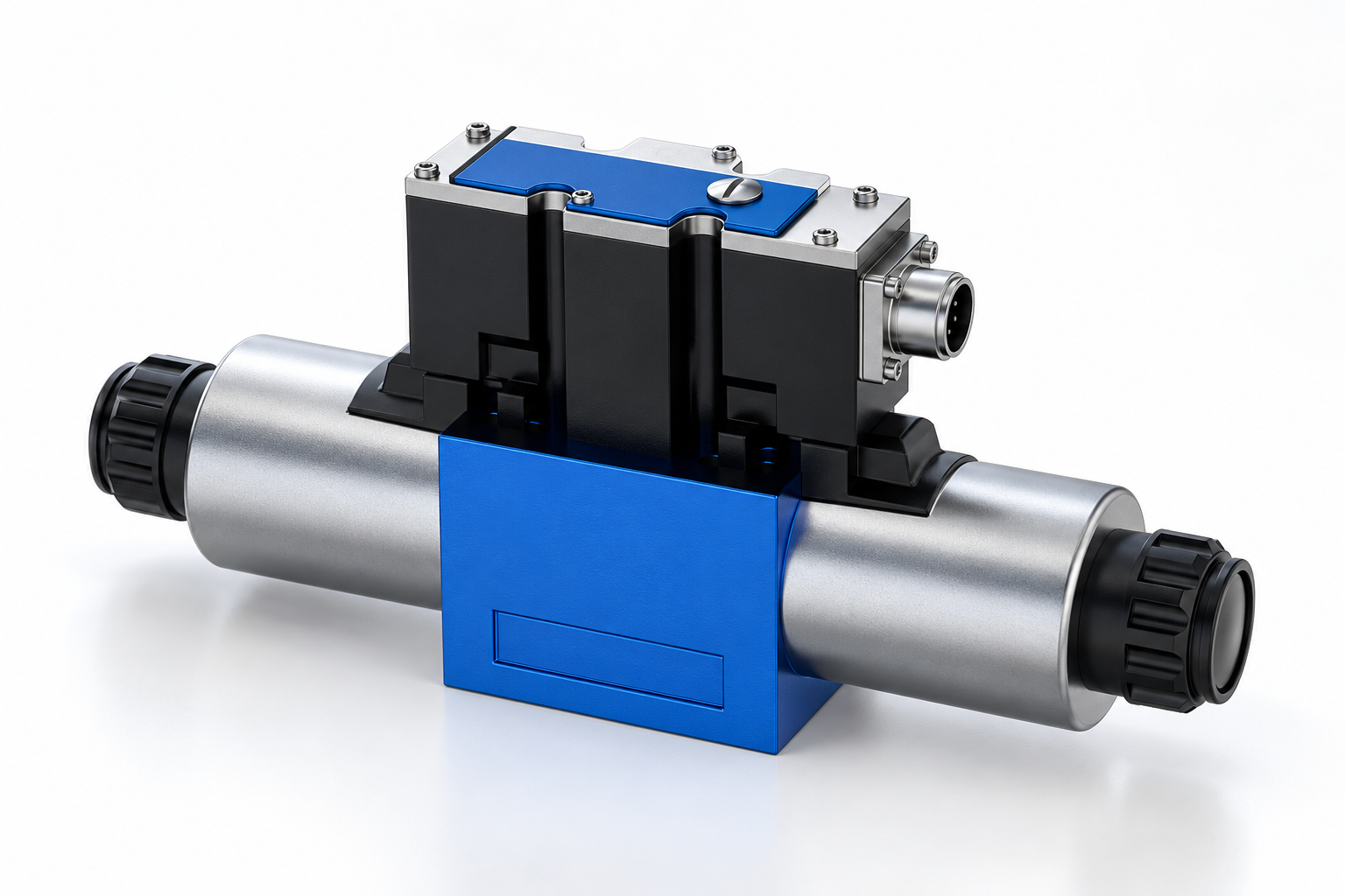
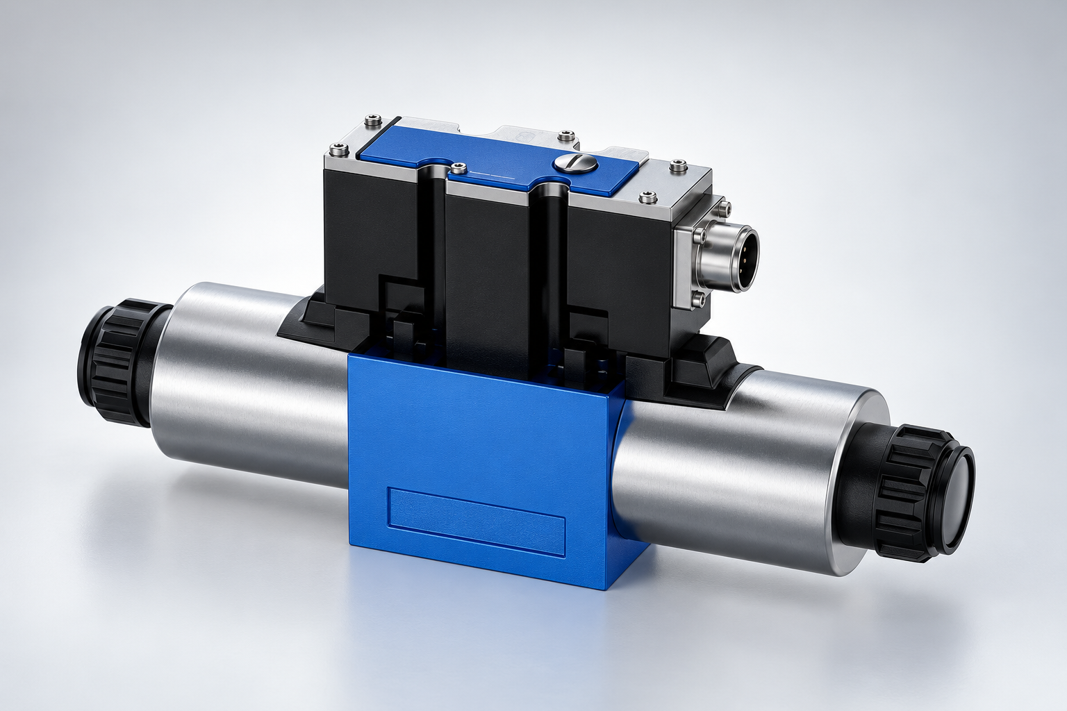
A broad product label such as directional valve or piston pump cannot establish an exact target. Clearances, controls, operating conditions and construction differ within a family. A proportional valve illustration can identify the exterior family, but it does not disclose every internal control feature or prove that a generic servo-valve recommendation applies to that order.
When several component requirements differ, the system designer must reconcile them into an achievable specification that protects the applicable components. Do not average the codes. Confirm how filtration, sampling, startup practices and monitoring will demonstrate compliance where the requirement matters. Ask the supplier to explain any missing fluid or component information rather than accepting a guessed target.
Use an evidence checklist instead of a universal target chart
| Component or system condition | Evidência a solicitar | Practical verification | What the code cannot establish alone |
|---|---|---|---|
| Selected pump or motor | Exact configuration and documented fluid-cleanliness requirement | Representative circulating-fluid sample at the agreed duty | A safe target for every product in the family |
| Directional valve | Model-specific requirement and operating conditions | Sample location relevant to the fluid reaching the valve | Whether the circuit function and ordered spool are correct |
| Proportional or servo function | Control configuration, documented cleanliness and fluid limits | Trend data plus command and motion behavior | That a control fault is caused by particles |
| New or repaired assembly | Installation cleanliness, preservation and commissioning requirements | Agreed inspection and sampling after commissioning | That new oil or a sealed component is contamination-free |
| Existing system with a rising count | Comparable samples, maintenance events and operating history | Repeat sample and supporting wear or fluid analysis | Particle origin, water content or chemical degradation |
| Acceptance or warranty enquiry | Written target, sampling method, point and response procedure | Compare valid results with the agreed specification | A contractual limit inferred from a generic online chart |
Supporting technical context: ISO 4406:2021 sample: solid-particle coding method, NPTEL: hydraulic filtration and contamination control. This evidence checklist does not establish a product rating or universal acceptance limit.
This is an original procurement and verification checklist. ISO 4406 supplies the particle-coding framework; the NPTEL filtration teaching supports the separation between contamination measurement and filtration-system choices. Specific target values must come from the actual equipment documentation.
Make the sampling location part of the specification
A report is only useful if the sample represents the condition being assessed. Fluid taken from a stagnant pocket, a dirty drain opening or an unclean container can produce a result dominated by the sampling method. Define the port, machine state, sampling procedure and container requirements before comparing results.
For an operating circuit, use the equipment's approved sampling procedure and a location selected by the responsible engineer or laboratory. Record whether the sample represents fluid upstream or downstream of a filter. A downstream result cannot automatically describe the contamination entering every component elsewhere in the machine.
If a safe, approved sampling point is unavailable, do not improvise by opening a pressurized fitting. Arrange a suitable procedure or port under authorized maintenance conditions. Include hazardous-energy isolation and rated sampling equipment in the service plan. The aim is repeatable evidence obtained safely, rather than a report with an impressive-looking code.
Keep laboratory method and sample handling consistent
Choose a laboratory capable of the requested particle-count method for the particular fluid. Tell it about the fluid type, unusual additives, suspected water or aeration and any conditions that could affect the measurement. Request the standard edition, units, raw cumulative counts and laboratory comments where available.
Air bubbles, water droplets and some fluid or sample characteristics can complicate optical counting. That does not mean every unusual count is false, nor does it justify discarding inconvenient results. Ask the laboratory to investigate potential interference with a suitable method and documented preparation instead of silently changing the reported code.
Keep sampling bottles, transfer tools and handling procedures consistent across the trend. Label the sample with equipment identity, point, date, fluid temperature, operating state and recent maintenance. A photograph of clear oil is not a substitute for counting fine solid particles; conversely, a particle code is not a substitute for investigating visibly abnormal oil.
Choose filtration using more than a micron label
A filter described only by a micron number does not fully establish its removal performance. Review the relevant efficiency information, flow capacity, permissible differential pressure, fluid compatibility and operating temperature. Check the installed element identity and whether a bypass is present. Use the actual filter manufacturer's data rather than extrapolating from the ISO code.
A finer element can change differential pressure and bypass behavior, especially during cold startup or as dirt accumulates. Evaluate its location in the circuit and the available pressure margin. Do not fit an arbitrary finer suction element to pursue a lower code if it could undermine the pump's permitted inlet conditions.
Pressure, return and offline filtration perform different roles. Their effectiveness depends on the routing, contamination source and machine operating pattern. Define an achievable target and a monitoring plan, then select equipment that can maintain it. NPTEL's filtration reference provides system context without assigning a universal filter size to every Prance assembly.
Control contamination throughout the component lifecycle
Include receiving, storage, installation, top-up and repair in the plan. Keep connection openings protected until the approved installation step, use compatible clean handling materials and control the cleanliness of fill equipment. Request preservation and packaging information when a component will be stored before use.
New oil should be assessed against the equipment's requirement rather than assumed ready for every sensitive circuit. Verify the receiving and transfer process. Document the fluid identity and avoid mixing products merely because their viscosity grade matches; compatibility and fluid condition require separate confirmation.
After a repair, do not rely on the repaired component alone to solve an existing contamination problem. Investigate the source and any debris remaining elsewhere in the circuit. Plan cleaning, filtration and verification with the responsible engineer. Keep the approved procedure and acceptance result together so that subsequent technicians can understand what was actually done.
Interpret a trend and respond to an exception
A useful trend contains comparable sample points, methods and machine conditions. Annotate filter changes, oil replacement, component failures and major maintenance. If a code rises after a repair, check the sampling validity and recent work before assigning a cause. If it continues rising under comparable conditions, escalate the investigation.
Agree a response process before the first exception. Depending on the machine's risk and equipment instructions, actions may include verification sampling, examination of filtration, contamination-source investigation or restricted operation. This guide does not establish a universal shutdown threshold. The operating decision belongs to the responsible machine and maintenance authority.
Do not declare a problem solved merely because one follow-up sample looks cleaner. Confirm that the improvement persists and that the relevant component requirement is satisfied at the agreed location and duty. Keep the repair evidence, filtration changes and repeat results traceable.
Prepare an RFQ that can receive a meaningful answer
For a Prance pump, motor or valve enquiry, state the exact component family, circuit role, pressure and flow duty, fluid, temperature range and current cleanliness evidence. Include the sampling method and point, plus any existing equipment requirement. Request the selected configuration's documented requirement and any installation or commissioning conditions.
Ask the supplier to distinguish a recommended operating cleanliness level from a test report or an unqualified service-life claim. If no target is available, retain that uncertainty and obtain the information needed by the system designer. Do not convert an unrelated catalog chart into a Prance warranty or specification.
Store the final target, supporting document revision, laboratory method and response plan with the purchase record. This turns a slash-separated code into a usable maintenance and acceptance process, while preserving the separate responsibilities of component selection, system design and fluid analysis.
Perguntas frequentes
Does ISO 4406 specify one cleanliness target for all hydraulic systems?
No. It provides a coding method for solid-particle contamination. The applicable target must be selected from the actual component and equipment requirements, operating duty and agreed verification process.
Are the three numbers separate particle-size bands?
In the usual automatic-count format they represent cumulative counts at the stated calibrated thresholds. A larger particle contributes to the smaller-threshold counts as well. Do not add the three cumulative values as independent particle populations.
Does a cleaner code prove that the oil is healthy?
No. A particle code does not by itself measure water, viscosity, oxidation, additive condition or every other fluid-health issue. Use the additional tests appropriate to the equipment and suspected problem.
Can I select a filter from the ISO code and a micron label alone?
No. Review efficiency, flow, pressure differential, bypass behavior, compatibility and circuit location. Verify that the selected arrangement can meet the actual target without creating a different operating problem.
What should I do when a result crosses the agreed target?
Follow the equipment's response procedure, confirm sample validity and investigate the trend and recent events. Record corrective work and obtain appropriate repeat evidence. A single unexplained retest should not be treated as proof that the root cause has been removed.
Related products and engineering guides
4WRAE proportional valve, hydraulic valve range, proportional valve deadband measurement, directional valve leakage diagnosis. Provide the circuit, fluid, duty and exact ordered configuration when requesting component-specific data.
University lesson: Lecture 36 : Introduction to hydraulic accessories
This NPTEL university lecture explains hydraulic accessory functions, including the system context for filtration and fluid handling. It supplies operating background, not an ISO cleanliness target or a laboratory foam-test method.

Technical references
- ISO 4406:2021 sample: solid-particle coding method
- NPTEL: hydraulic filtration and contamination control
- NIOSH: hazardous-energy isolation
Sources support the stated principles and method scope. Illustrative inputs and another manufacturer’s documents do not establish Prance component ratings, warranties or brand affiliation.