Wenzhou Prance Hydraulic Equipment Co., Ltd

Shuttle Valve vs Check Valve: Pressure Selection and One-Way Isolation
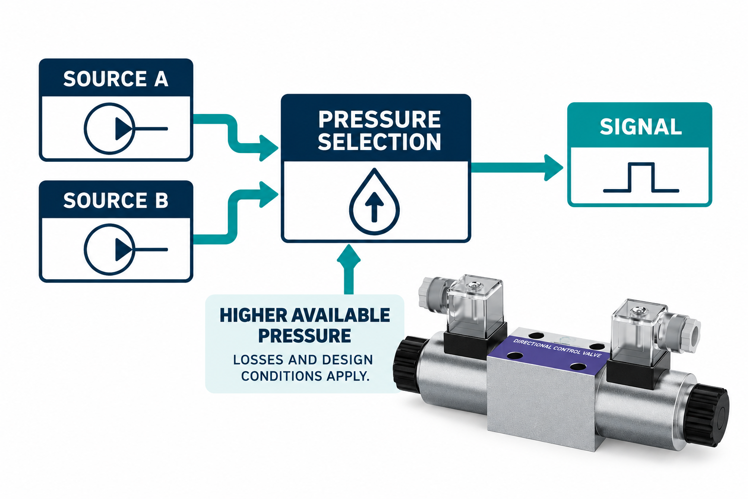
A shuttle valve selects between pressure sources, while a check valve permits flow in one direction and restricts it in the opposite direction under its specified conditions. A common pressure-selecting shuttle has two source connections and a selected connection: the higher available source pressure moves the internal element to isolate the other source. A simple check valve has a different task, usually involving a forward flow path and reverse isolation. Neither name establishes flow capacity, zero leakage, response time, or suitability for an unidentified hydraulic circuit.
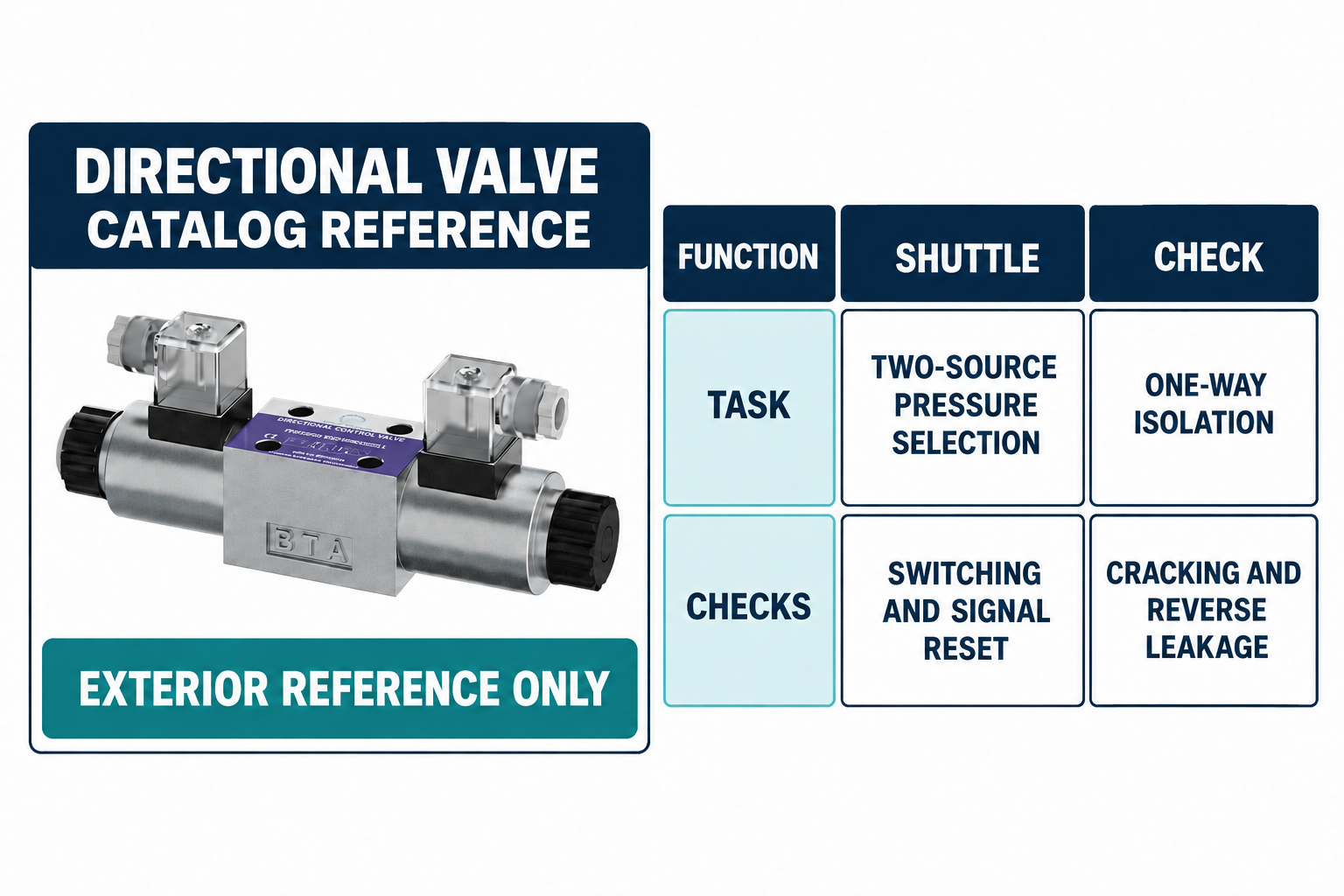
The 4WE photograph is a directional-valve exterior reference for the surrounding control system. It does not depict a shuttle or check valve, and the comparison illustrations do not claim that the pictured valve includes either additional function.
Start with the question the circuit must answer
A pressure-selection task asks which source should supply a pressure signal or another approved selected path. A one-way-isolation task asks which direction flow may take and what reverse condition must be resisted. These questions can occur near each other in a circuit, but they are not identical.
Identify the source connections, selected or receiving region, pressure range, fluid, expected flow, and all relevant operating states. Decide whether the path carries a small control signal or significant working flow. A valve suitable for a pressure signal is not automatically suitable for the main pump delivery. The function must be clear before comparing catalog parts, symbols, or port sizes.
Follow the common shuttle-selection principle
In a common higher-pressure selection arrangement, pressure from one source moves the shuttle toward the opposite side, restricting the competing source and connecting the selected source to the common path. When the pressure relationship changes sufficiently for that design, the shuttle can move to the other position.
This is pressure selection, not pressure addition. Two source pressures do not become their arithmetic sum at the outlet. Actual selected pressure can differ from the available source pressure because of flow, pressure loss, leakage, switching behavior, and the design’s characteristics. Use the component documentation to understand the required differential and behavior around switching rather than treating an ideal logic description as a measured performance curve.
Do not assume a predictable position at equal pressure
When the sources are close in pressure, actual behavior depends on the design, the previous condition, friction, fluid effects, and other operating details. A small nominal difference does not justify a universal claim that every shuttle will select a particular source immediately or with no transition effects.
Where a stable selected signal matters to a controller, define the expected switching conditions and examine the chosen valve’s performance. Consider pressure fluctuations and the effect of trapped or slowly decaying signals. A simplified diagram should not be treated as proof of switching speed, absence of chatter, or a preferred-source priority function. If priority rather than higher-pressure selection is required, identify that as a separate functional requirement.
Follow the check valve’s forward and reverse behavior
A basic check valve opens its permitted direction when the applicable pressure and force conditions are met. A spring-loaded design may specify cracking behavior and pressure drop over flow. Reverse pressure generally acts to close the intended reverse path, but the allowable leakage and operating limits still need the exact specification.
Cracking pressure is not the complete pressure-loss curve. A part that begins to open under one condition can produce a different pressure drop while passing the required flow. Likewise, describing a valve as non-return does not establish perfect sealing in every condition. Match forward flow, reverse pressure, fluid conditions, leakage requirements, and any other relevant characteristics instead of selecting solely from connection size.
Compare the functions in a practical table
| Pergunta | Common shuttle-selection function | Basic check-valve function |
|---|---|---|
| Main task | Select a path from competing pressure sources | Permit forward flow and restrict reverse flow |
| Typical basic connections | Two sources and a selected connection | Forward inlet and outlet |
| Selection driver | Relative source conditions and valve design | Forward differential and closing forces |
| Common misunderstanding | It combines or adds two pressure sources | It guarantees zero reverse leakage or zero forward loss |
| Important verification | Switching, isolation, selected-signal behavior, and reset path | Cracking behavior, flow loss, reverse condition, and leakage |
| Product choice | Match signal or working-flow duty explicitly | Match permitted and blocked directions with actual duty |
The table describes basic functions. Pilot-operated, combined, priority, low-pressure-selecting, or other specialized arrangements require their own documentation.
Distinguish a shuttle from an operated selector or diverter
An operated selector may change connections according to a manual, electrical, or pilot command. A common shuttle selector responds automatically to the pressures acting on its sources. A diverter or directional valve can route working flow through a different arrangement entirely. Similar words in product listings do not establish that these functions are interchangeable.
Use the actual circuit symbol and operating description. Specify whether the machine needs operator choice, a commanded state, selection of a pressure signal, or a flow-routing function. Replacing one with another based on port count can alter both normal behavior and what happens when supply conditions change. Keep the functional requirement explicit before comparing footprints or fittings.
Understand why two checks do not prove full equivalence
Two check-valve paths feeding a common region can provide a form of source isolation and may support a pressure-selection purpose in a suitably designed circuit. That does not establish that every two-check arrangement behaves like every shuttle valve. Forward losses, leakage, switching, volume, return behavior, and the way the common region is relieved or reset can differ.
Review the complete operating description rather than treating a schematic resemblance as a general substitution rule. In particular, ask what happens when both sources fall and whether the selected signal can return to its intended condition. A pressure that remains trapped can have a different consequence from a signal that follows a source downward. The appropriate path must be designed, not improvised from an unexplained tee and two available valves.
Evaluate signal reset and reverse behavior explicitly
The selected connection may interact with a pilot or control circuit whose state depends on pressure rising and falling at the intended time. A source-selection device alone does not describe every return or discharge path. Consult the exact design to determine permitted reverse behavior and the connections needed for the control to reset.
Do not assume that a hydraulic circuit can use the venting behavior of a pneumatic example without further review. University pneumatic OR-logic examples are useful for explaining selection logic, but their medium, pressure limits, discharge paths, and component requirements are not a hydraulic product specification. Keep the transferable logic principle separate from the fluid-power implementation and its approved details.
Match the valve to signal flow or working flow
A pressure signal can require little sustained flow while still needing controlled response, leakage, and reset behavior. A working-flow path must also handle the intended delivered flow and associated pressure losses. The same nominal pressure range does not make those duties equivalent.
Specify flow and pressure conditions for every relevant state, including transitions. Consider the volume connected to the selected path and any pressure changes created by switching. Where a source is isolated, identify its permissible reverse exposure and any trapped region. Do not use a small signal-selection component in a main flow path solely because its threaded connections can be adapted to fit.
Include fluid condition and installation identity
Contamination, fluid compatibility, temperature, and installation conditions can affect the intended function. Obtain the complete component code, port identification, applicable flow direction, and documentation. Do not infer these from a general exterior photograph or from where a connection happens to be located on a manifold.
Keep mounting, connection, and functional reviews separate. A replacement that screws into the available cavity can still have different behavior or limits. Confirm the correct assembly and use the approved installation method, including cleanliness and the required inspection. If the original arrangement is uncertain, resolve the circuit and component identities before adding parts or changing connections to make an observed symptom disappear.
Verify both selection and loss of selection
Testing should demonstrate the relevant source conditions, the selected pressure, source isolation, and return or reset behavior under the approved procedure. Use suitable test points and instruments, record temperature and flow conditions where relevant, and define the observations that require stopping. Do not intentionally cross-connect sources or defeat isolation to demonstrate which pressure is higher.
Address stored hydraulic and mechanical energy before service work. A selected or isolated region may retain pressure after the main supply is stopped. Retain the actual component identity, circuit state, measurement locations, and results. A single stable pressure reading with one source active does not establish behavior during source changes or after both sources are removed; record the full required test boundary.
Perguntas frequentes
Does a shuttle valve add the two inlet pressures?
No. A common higher-pressure shuttle selects a source and isolates the competing path. Actual selected pressure depends on the component and operating conditions, including pressure loss and leakage. It is not the arithmetic sum of the supplies.
Is a shuttle valve the same as a check valve?
No. A shuttle commonly addresses selection between sources, while a basic check addresses one-way flow. Some arrangements combine related isolation functions, but complete behavior must be compared rather than inferred from the names.
Can two check valves replace a shuttle?
Only after the complete circuit and required behavior are reviewed. Selection, flow losses, reverse behavior, leakage, and signal reset may differ. A visually similar arrangement is not evidence of universal equivalence.
Is the selected signal guaranteed to reset when supply stops?
Not from the valve name alone. Determine the actual discharge or return path and the component’s documented reverse behavior. A trapped signal and a properly reset signal can produce different control outcomes.
What should a supplier receive with a selection request?
Provide the circuit, source and selected-region conditions, flow duty, fluid and temperature, switching and reset requirements, allowable losses and leakage, and the actual installation interface. State whether the path carries a control signal or working flow.
Produtos e recursos de engenharia relacionados
The Directional Valve 4WE catalog exterior is used as the real product reference in these explanatory images. It does not establish the approved service method, optional construction, or operating limits for an individual order. Confirm the complete code and its documentation. Related resources: Válvula Direcional 4WE, Área de válvulas hidráulicas, Como preparar uma questão sobre a aplicação de uma válvula de retenção hidráulica para revisão, Válvula Seletora Hidráulica: Escolha o Percurso de Circuito Correto Sem Misturar Funções de Válvulas, Como é que as condições do centro da válvula de distribuição afetam um circuito?.
Sources and limits of this guide
The university resource supports the component operating principles. NIOSH supplies hazardous-energy prevention context; exact machine isolation and component service requirements still need their approved procedures. Sources explain general operating principles, not performance ratings or optional features of the pictured catalog component.
- NPTEL: Fundamentos de Hidráulica e Pneumática Industrial
- NIOSH: prevenção de lesões causadas por energia perigosa
- NPTEL: shuttle-valve OR logic in a pneumatic teaching example; logic principle only, not hydraulic ratings
University lesson: operating principles
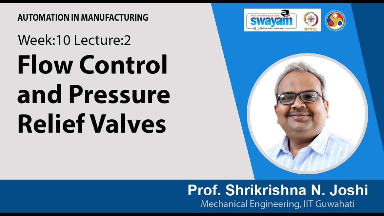
NPTEL IIT Guwahati presents Lec 31: Flow control and pressure relief valves. The lesson supports the valve operating principles used in the engineering discussion; it is not a model-specific repair, storage, or installation approval.