Wenzhou Prance Hydraulic Equipment Co., Ltd

Variable-Speed Hydraulic Pump Drives: Low-Speed Limits and Control
A variable-speed hydraulic pump drive needs an approved low-speed operating envelope and a control strategy that respects it. There is no universal minimum rpm that makes every pump safe during standby or low flow demand. The drive must coordinate pump lubrication and filling requirements, useful delivered flow, pressure stability, electric-motor thermal limits and transitions back to working speed. This guide focuses on how to implement that coordination: speed floors, demand handling, pressure-loop behavior, standby choices and acceptance tests. The separate pump minimum-speed guide explains the underlying component limits; a drive controller cannot override those limits.
Separate the pump limit from the machine’s control decision
The pump manufacturer defines permissible operation for the exact pump code and stated conditions. The machine designer then chooses a speed command that stays within that envelope while meeting the load demand. A controller parameter labelled minimum frequency is merely a setting. It does not prove that the pump, electric motor or machine is suitable at the resulting shaft speed.
Obtain the permitted speed conditions before programming the drive. Continuous running, brief transitions, startup and stopping may have different requirements. Pressure, viscosity, temperature and inlet conditions can change the permissible operating region. Record those conditions with the limit instead of storing a single unqualified rpm value in the commissioning sheet.
A low flow demand does not automatically authorize a proportionally low speed. For a fixed-displacement pump, theoretical flow falls with speed, but useful flow also depends on leakage and operating conditions. The machine may reach a point where further speed reduction no longer gives stable pressure or the required delivery. That is a control boundary to evaluate, not evidence that a generic lower-speed setting will work.
Map the complete demand range before setting a speed floor
List the machine’s working states: high-flow motion, low-speed approach, pressure holding, cooling or circulation where required, standby and restart. Describe the required pressure and flow in each state and how long it lasts. A drive selected only for maximum flow can leave the low-demand states undefined.
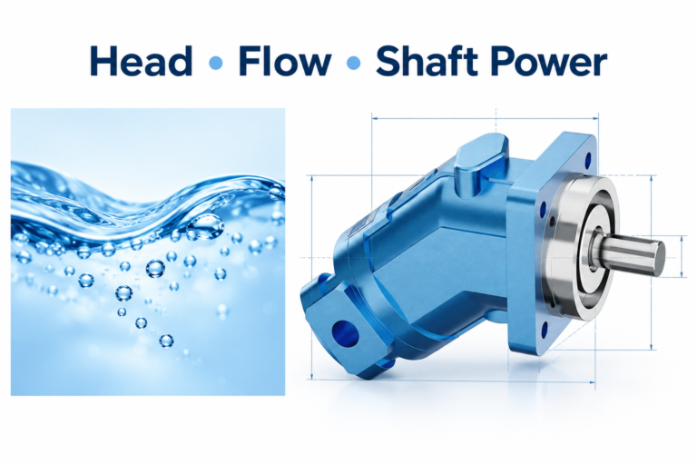
For a fixed-displacement pump, a useful starting relationship is theoretical flow Q = D × n / 1000, where Q is litres per minute, displacement D is cubic centimetres per revolution and speed n is revolutions per minute. Actual delivery differs because of leakage and the operating state. The equation describes displacement flow; it does not provide a permitted minimum speed or predict pressure stability.
As an illustrative calculation only, a hypothetical 20 cm³/rev pump turning at 600 rpm has a theoretical flow of 12 L/min. This is not an HG product rating or an approved operating point. If the machine needs only 2 L/min in a particular state, the equation does not justify reducing speed to 100 rpm. The actual pump envelope and the method of handling that low demand still require review.
For a variable-displacement pump, displacement control adds another input. The drive-speed loop and displacement or pressure controller may interact. Do not apply a fixed-displacement calculation as a complete model of that system. Establish which controller regulates pressure, which sets flow demand and how limits are coordinated.
Coordinate speed floors with the pressure loop
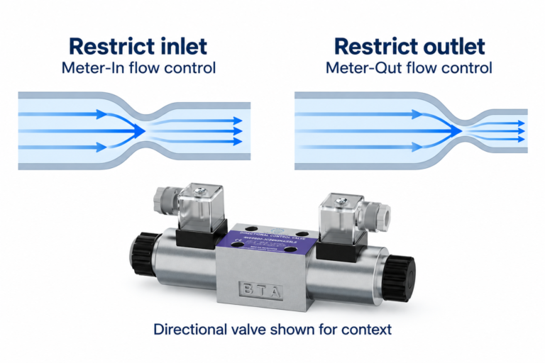
A pressure controller may request lower speed when demand falls. If the permitted speed floor is reached, the controller can no longer regulate pressure by reducing speed in the same way. The machine needs a defined response to that saturation. It might use an approved unloading state, a controlled stop, a different pump arrangement or another engineered strategy.
Define how the pressure controller behaves at its limits. Integral accumulation during saturation can cause a delayed response or overshoot when demand returns. Controller designers commonly address this through appropriate limit handling and tuning, but the implementation must match the actual drive and machine. Do not copy gains or ramp times from an unrelated hydraulic installation.
Commanded speed and measured shaft speed should remain distinguishable in the records. A drive may limit current or torque during a pressure transient, so the shaft can respond differently from the requested ramp. A useful commissioning trace records pressure demand, measured pressure, requested speed, actual speed and any active drive limitation together.
O existente hydraulic pump minimum-speed guide covers component-level considerations. This article adds the control response when the machine asks for a condition below that approved boundary. Keeping those roles separate avoids treating a software setting as a substitute for component qualification.
Choose a standby strategy for the actual circuit
Continuous low-speed operation is one possible strategy, but it requires approval for the pump, drive motor and machine conditions. It can still generate heat if flow passes across a pressure difference. The lowest available command is therefore not automatically the lowest-energy or most reliable standby state.
An approved stop-and-restart strategy can reduce running time, yet introduces questions about pressure retention, restart delay, lubrication, load control and starting frequency. A stopped pump must not be assumed to hold a load. Valves, accumulators where fitted, and the machine’s energy-control arrangements need separate review.
Unloading can allow a running pump to deliver at lower pressure when working flow is not needed. Whether that is appropriate depends on the circuit. An unloading function must have a defined return to the working state and suitable pressure protection. It is not simply a permanent relief-valve bypass selected because it makes the pressure loop quieter.
Some applications have circulation, filtration, cooling, pilot or auxiliary flow requirements during standby. Those demands can set a practical floor even when the main actuator is stationary. Trace them from the schematic. Do not switch off the pump merely because the principal motion command has reached zero.
Include the electric motor and drive in the low-speed review
A variable-frequency or servo drive changes the operating conditions of the electric motor as well as the hydraulic pump. Torque demand, thermal behavior, cooling arrangements and permitted duty need confirmation for the selected motor and drive combination. A standard motor’s nameplate power alone does not establish continuous operation at every commanded speed.
Pressure demand produces pump shaft-torque demand. Reducing speed does not automatically remove that torque requirement. A drive can encounter a current or torque limitation while the hydraulic circuit is still asking for pressure. Record any limiting state and verify the motor’s applicable operating envelope with its supplier.
Also consider speed feedback, command resolution and low-speed stability. A requested small change in flow may correspond to a small speed change that the complete system cannot reproduce consistently under the stated load. Evaluate repeatability rather than assuming that a fine numerical command provides equally fine hydraulic control.
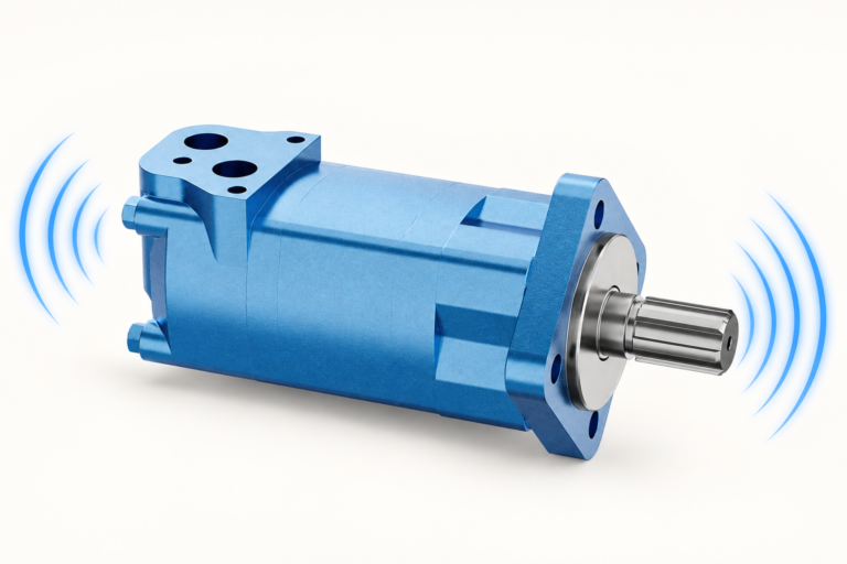
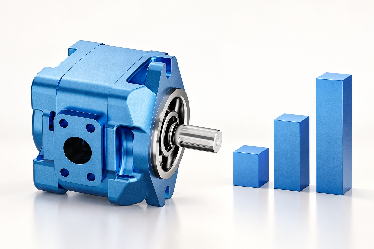
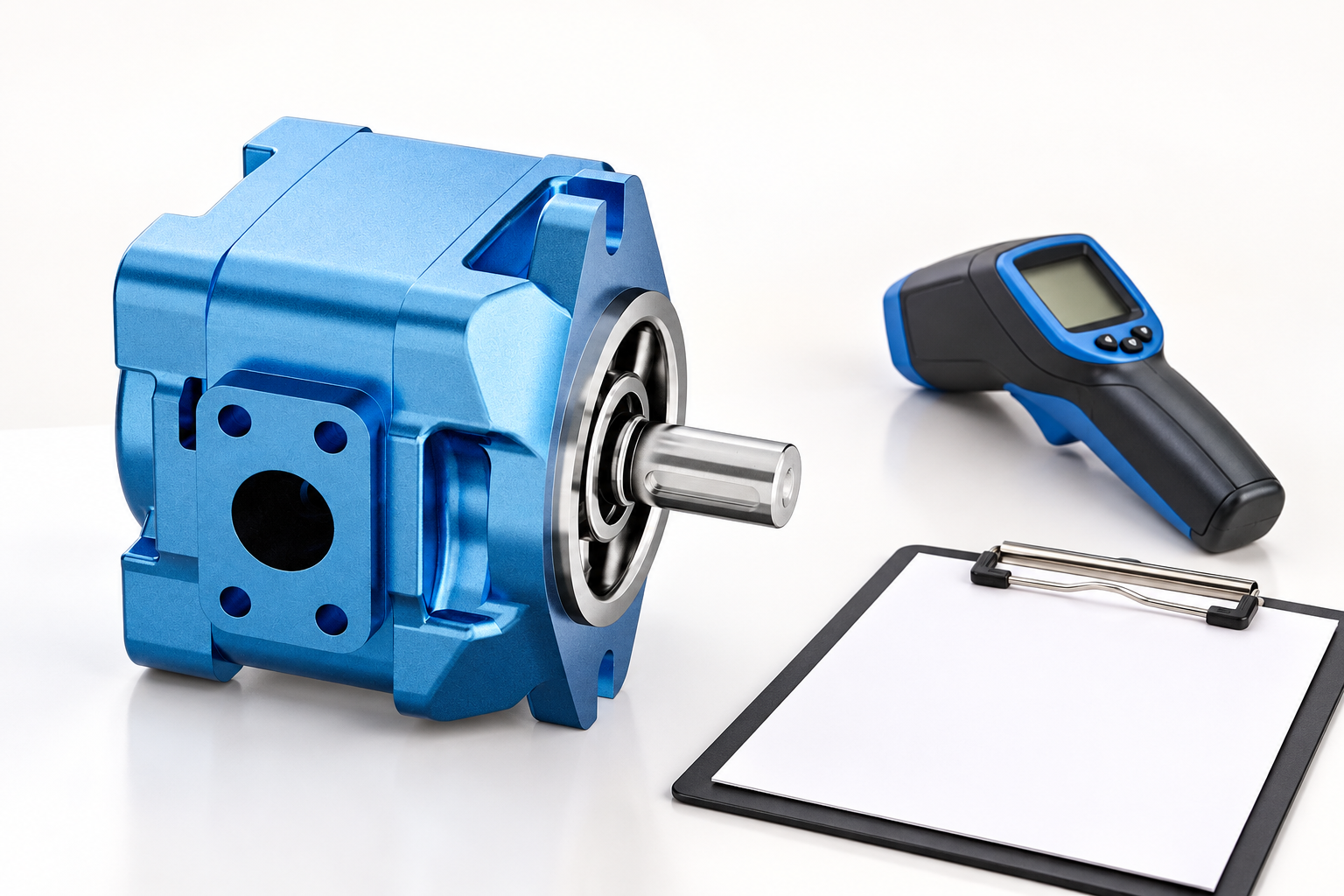
O HG internal gear pump product is the real exterior reference in the illustrations and is associated on this site with servo hydraulic applications. The photograph and general application description do not provide a qualified minimum speed for an individual pump.
Use a control-state review table
This table defines questions to resolve with the machine and component suppliers. It intentionally supplies no universal rpm, pressure, ramp or timing values.
| Machine state | Control question | Evidence required | Acceptance focus |
|---|---|---|---|
| Normal working demand | Can the commanded speed supply the duty within all component limits? | Pump envelope, drive capability and measured operating points | Flow and pressure achieved without limiting events |
| Demand below speed floor | What action occurs when pressure regulation reaches its lower speed limit? | Control-state logic and circuit review | Stable defined behavior without uncontrolled pressure rise |
| Continuous standby | Are lubrication, cooling and auxiliary flows adequate? | Approved pump and motor duty conditions | Temperature and pressure remain within documented limits |
| Stopped standby | What maintains the required safe machine state? | Load-control and stored-energy review | No assumption that a stopped pump holds the load |
| Restart after standby | How are speed, pressure and any valves sequenced? | Synchronized transition traces | Predictable response without unacceptable excursions |
| Loss of feedback or command | Which safe state is required and how is it reached? | Failure-response design and verification plan | Protective behavior remains effective |
Test transitions as well as steady operation
A steady low-speed point can look satisfactory while the transition into or out of it creates instability. Test the authorized range of initial pressure, load, fluid temperature and standby duration. Record what happens when demand disappears, when it returns and when the controller encounters a limit. Use a safe incremental plan rather than an abrupt exploratory command.
Track pressure and actual speed on the same timebase. Where useful, add delivered flow, drive current and relevant valve state. Instrument selection and acquisition rate must suit the event. A slow display can hide a transient, while a noisy unsynchronized record can suggest a control interaction that is not real.
Establish stop conditions and documented operating limits before testing. Stop for unexpected movement, a leak, abnormal vibration, rapidly increasing temperature or an approach to a component limit. Any change to a control parameter should have a stated purpose, an authorized range and a saved original value. Retain the resulting traces with the configuration revision.
O NIOSH hazardous-energy guidance applies to isolation and stored-energy control before opening lines or installing equipment. A zero-speed command is not an isolation procedure. Electrical supplies, stored hydraulic energy and movable loads must be addressed through the machine’s approved method.
Specify the supplier evidence needed for commissioning
Request a speed-pressure-temperature operating envelope for the exact pump, including applicable fluid and inlet conditions. Ask separately about continuous low-speed operation, start-stop duty and any installation requirements. Do not turn a maximum-speed specification into an assumed minimum-speed approval.
For the drive package, obtain the motor and drive torque-speed capability, cooling arrangement, permitted duty and relevant feedback requirements. For the machine, document the low-demand state logic, pressure-loop limits, auxiliary flow needs and restart requirements. These documents should describe a compatible operating region rather than three separate nominal ratings.
O gama de bombas hidráulicas supports component enquiries, and the swash-plate pump explanation describes why displacement-controlled arrangements differ from fixed-displacement speed control. Keep the selected pump type explicit when reviewing equations or controller behavior.
A complete acceptance record includes approved limits, parameter revision, test conditions, raw traces and unresolved restrictions. If the supplier has not approved a low-speed point, mark it as unverified and choose a permitted operating strategy. Do not label it acceptable because a brief test happened to finish without an obvious fault.
Perguntas frequentes
What minimum rpm should I set for a variable-speed hydraulic pump?
Use the approved operating envelope for the exact pump and conditions, then coordinate the drive and machine controls around it. There is no universal rpm value that applies to every pump or standby duty.
Can I calculate minimum speed from required flow alone?
No. Displacement and speed give theoretical flow, but useful delivery, lubrication, filling, thermal conditions and control stability still matter. A flow equation cannot establish component approval.
Is running slowly always better than stopping the pump?
Neither strategy is automatically preferable. Evaluate energy use, lubrication, auxiliary flow, cooling, restart demand and safe load control. Use the strategy approved for the complete machine.
Why can pressure fluctuate when the drive reaches its speed floor?
The controller may have reached the limit of speed-based regulation while demand continues to change. Review saturation handling, circuit state and the interaction of pressure, speed and any displacement control rather than adjusting gains blindly.
What should a low-speed commissioning report contain?
Include component codes, approved envelopes, fluid and temperature, demand states, control parameters, synchronized pressure and speed traces, active drive limits, stop conditions and any remaining operating restrictions.
Produtos e recursos de engenharia relacionados
The Internal Gear Pump HG for Plastic Injection Molding Machine catalog exterior is used as the real product reference in these explanatory images. It does not establish the approved service method, optional construction, or operating limits for an individual order. Confirm the complete code and its documentation. Related resources: Bomba de Engrenagens Internas HG para Máquina de Moldagem por Injeção de Plástico, gama de bombas hidráulicas, Velocidade Mínima da Bomba Hidráulica: Limites de Lubrificação, Controlo e Arranque, Princípio de Funcionamento da Bomba de Prato Oscilante: Da Rotação ao Caudal Variável.
Sources and limits of this guide
NPTEL supports hydraulic component principles. The FAA handbook supports general hydraulic flow, pressure, fluid and compliance concepts, without supplying industrial settings or timing limits. NIOSH supports hazardous-energy control. Controller tuning, brake sequence and component operating limits require the approved machine and supplier documents.
- NPTEL: Fundamentos de Hidráulica e Pneumática Industrial
- FAA: Aviation Maintenance Technician Handbook, Airframe Volume 2, hydraulic-system principles
- NIOSH: prevenção de lesões causadas por energia perigosa
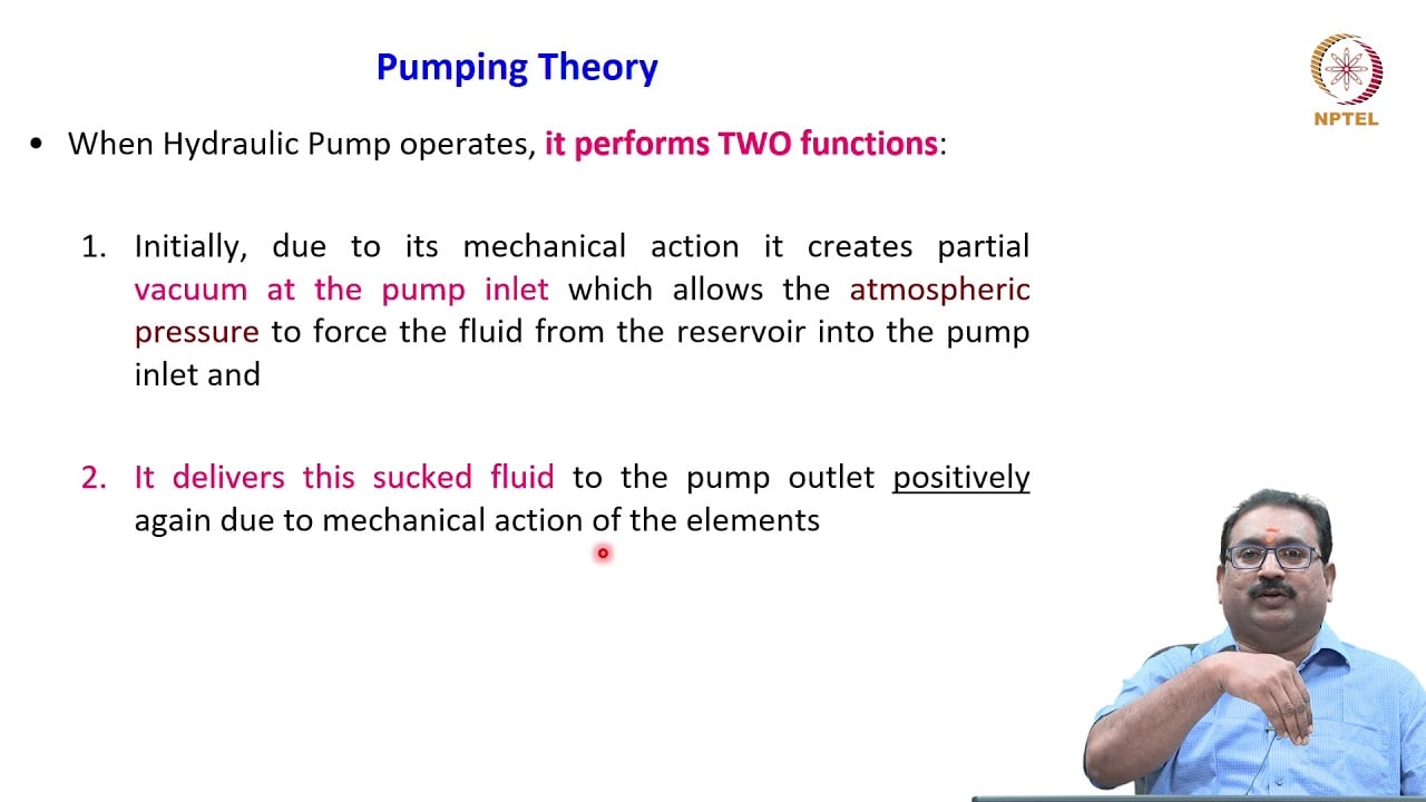
University lesson: operating principles
NPTEL-NOC IITM presents 3.2 – Hydraulic Pumps. The lesson supports the pump operating principles used in interpreting displacement flow and a variable-speed drive control boundary used in this discussion; it is not a model-specific performance or installation approval.