Wenzhou Prance Hydraulic Equipment Co., Ltd

Hydraulic Mixer Motor Selection: Viscosity Changes and Loaded Starts
Hydraulic motor mixer selection should start with the mixer’s required torque and speed through the whole batch, especially the most difficult permitted loaded start. Then match motor displacement, usable pressure difference, flow supply, shaft support, and heat rejection. Do not select from nominal power alone or assume that one viscosity value represents every process stage. A motor that mixes a warm, moving batch may fail to restart settled material. Conversely, increasing displacement without checking available flow can reduce mixer speed below the process requirement.
1. Define the batch states that change the load
Describe the material, working volume, impeller geometry, speed range, and process temperature. Identify whether the batch becomes thicker during addition, cools during a pause, contains settling solids, or changes its apparent viscosity with shear. These conditions influence the torque-speed envelope that the drive must meet. They do not justify a universal multiplier for starting torque.
Separate at least the empty or low-load check, normal mixing, the highest permitted operating load, and restart after the maximum allowed pause. If a settled batch must never be restarted, document that operating restriction and the recovery procedure. Do not size the drive for an undefined worst case while leaving operators to decide what a safe restart means.
The NPTEL agitation lesson explains that mixing power depends on fluid and equipment variables, not viscosity in isolation. Use a process designer’s calculation, applicable impeller data, or a representative test to establish the load. A small laboratory stirrer result is not automatically transferable to a production vessel with different geometry.
2. Keep process viscosity separate from hydraulic-oil viscosity
The material in the mixer and the oil driving the motor are different fluids with different roles. Process viscosity affects the load at the impeller. Hydraulic-oil viscosity affects the motor, supply losses, leakage, lubrication, and cold-start behavior. Both can change during operation, but they must not be entered as the same selection input.
For a non-Newtonian process material, a single viscosity number without temperature and measurement conditions can be misleading. Ask the process specialist which apparent viscosity or rheological model applies to the relevant shear conditions. Avoid a promise that twice the viscosity always requires twice the motor torque; that relationship depends on the impeller and flow regime.
For the hydraulic side, use the motor’s documented fluid and operating limits. A hot batch can coexist with relatively cool hydraulic oil, or a warm hydraulic system can drive a cold settled batch. Evaluate those cases independently. An oil-grade change cannot resolve an incorrect estimate of process starting torque.
3. Convert required torque into a motor operating point
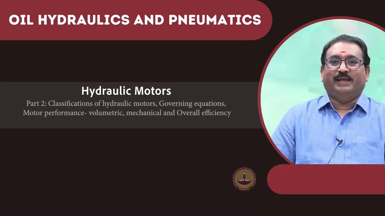
For preliminary steady-state motor calculations, T = delta_p × V_d × eta_m / 62.83, where torque T is in N·m, pressure difference delta_p is in bar, displacement V_d is in cm³/rev, and eta_m is mechanical efficiency as a fraction. Required inlet flow is Q = n × V_d / (1,000 × eta_v), with speed n in rpm and Q in L/min. The NPTEL motor exercises provide the corresponding torque, flow, and efficiency relationships.
Use pressure difference across the motor, not only pump outlet pressure. Return-line pressure reduces usable difference and may independently affect seal or drain requirements. Allow for the actual supply circuit rather than assuming the relief setting is available continuously at the motor ports.
These equations are preliminary sizing tools. A running mechanical-efficiency assumption does not establish breakaway performance. Obtain starting-torque data or an applicable performance envelope for the proposed configuration, fluid condition, and pressure. Check continuous and intermittent limits separately, including the permitted duration and repeat rate of peak events.
4. Work a direct-drive example without treating it as a rating
Assume, for teaching only, a mixer needs 500 N·m at 60 rpm during one running state. Assume usable motor pressure difference of 160 bar, mechanical efficiency of 0.85, and volumetric efficiency of 0.90. The calculated displacement requirement is approximately 231 cm³/rev. A hypothetical 250 cm³/rev motor under those assumptions would produce about 541 N·m and require 16.7 L/min at 60 rpm.
The shaft output at the required 500 N·m and 60 rpm is approximately 3.14 kW, using P = T × n / 9,550. If the same mixer instead requires 750 N·m to start after an allowed pause, the 541 N·m running estimate cannot demonstrate that it will start. The proper next step is a starting-performance check or a reviewed change to displacement, reduction, pressure availability, or the process restriction.
None of these numbers is a BMT specification or a recommendation to operate at a particular pressure. The assumed efficiencies are illustrative, and the calculation does not include a gearbox, transient losses, or an allowance approved by the machine designer. A catalogue size close to 250 cm³/rev must still pass the actual torque-speed and duty checks.
5. Compare direct drive with reduction
A reduction gearbox can let the hydraulic motor operate faster while the mixer turns slowly. For a reduction ratio i defined as motor speed divided by mixer speed, mixer torque is approximately motor torque × i × gearbox efficiency. That can change the motor operating region and displacement requirement. It also adds gearbox losses, backlash, support requirements, lubrication, and additional torque limits.
Direct drive avoids the gearbox but may require a motor suited to the required low-speed stability and starting duty. A low average rpm does not prove smooth rotation at that speed under a fluctuating material load. Ask for the relevant minimum stable-speed or performance information under comparable conditions.
Compare the complete alternatives using the same mixer output requirement. Check gearbox peak torque and output bearing loads where reduction is used. Do not increase the hydraulic motor size until a mechanically undersized gearbox or agitator shaft becomes the limiting component. The process, motor, gearbox, coupling, and shaft support must form one reviewed drive train.
6. Use a selection table that follows the batch
This qualitative table is an author-developed engineering checklist. The motor relationships come from the NPTEL hydraulic-motor exercises, while the agitation lesson supplies the basis for treating fluid and impeller variables together. It contains no manufacturer ratings.
| Batch or installation condition | O que verificar | Porque é que altera a seleção |
|---|---|---|
| Restart after a permitted pause | Defined breakaway load and motor starting performance | Running torque may not demonstrate restart capability |
| Thickening during addition | Torque and required speed through the addition sequence | The initial low-load state may not govern |
| Lowest commanded mixing speed | Stable motor rotation and process mixing requirement | More displacement can reduce speed when flow is limited |
| Reversal or controlled stopping | Inertia, permitted deceleration, pressure transients, and circuit protection | Normal running pressure does not define every event |
| Long mixing stage | Continuous ratings and measured or calculated losses | An intermittent torque rating cannot cover sustained operation |
| Overhung impeller or vertical shaft | Radial load, thrust, bearing arrangement, and coupling | cURL Too many subrequests by single Worker invocation. To configure this limit, refer to https://developers.cloudflare.com/workers/wrangler/configuration/#limits |
| Alta pressão de retorno | cURL Too many subrequests by single Worker invocation. To configure this limit, refer to https://developers.cloudflare.com/workers/wrangler/configuration/#limits | cURL Too many subrequests by single Worker invocation. To configure this limit, refer to https://developers.cloudflare.com/workers/wrangler/configuration/#limits |
cURL Too many subrequests by single Worker invocation. To configure this limit, refer to https://developers.cloudflare.com/workers/wrangler/configuration/#limits.
cURL Too many subrequests by single Worker invocation. To configure this limit, refer to https://developers.cloudflare.com/workers/wrangler/configuration/#limits
cURL Too many subrequests by single Worker invocation. To configure this limit, refer to https://developers.cloudflare.com/workers/wrangler/configuration/#limits.
cURL Too many subrequests by single Worker invocation. To configure this limit, refer to https://developers.cloudflare.com/workers/wrangler/configuration/#limits.
cURL Too many subrequests by single Worker invocation. To configure this limit, refer to https://developers.cloudflare.com/workers/wrangler/configuration/#limits.

8. Account for speed-control and thermal losses
A mixer may spend much of a batch at reduced speed. Determine how the supply circuit achieves that speed: a suitable variable-flow source, a controlled valve arrangement, or another approved system. Flow passing across a pressure drop produces heat, so a small shaft-power requirement does not necessarily imply low hydraulic heat load.
Estimate losses over the real cycle and include pump, motor, valve, line, and any gearbox contributions within the chosen boundary. Confirm cooler capacity and reservoir behavior for the operating environment. The motor’s efficiency alone cannot size the complete cooling system, and a larger oil reservoir does not eliminate sustained heat generation.
Watch for a misleading commissioning result: an initially cool unit completes a short empty run, then loses speed as a loaded batch and hydraulic system warm up. The acceptance procedure should include the intended duration and thermal condition. Compare measured behavior with documented limits rather than inventing a universal acceptable housing temperature.

9. Define safe restart and final acceptance
Before clearing a jam, inspecting a coupling, or entering a vessel, isolate the drive and address stored hydraulic, gravitational, and mechanical energy through the approved procedure. The NIOSH lockout guidance below emphasizes releasing or blocking stored energy and verifying isolation. A stopped mixer can still move unexpectedly, and the product itself may introduce additional process hazards.
Commission with the machine designer’s permitted sequence and exclusion zones. Verify direction, commanded speed, pressure difference, leakage or drain arrangement where applicable, and response through the defined batch states. Do not deliberately stall the agitator or reverse a settled batch unless that operation is explicitly permitted.
For the final selection request, send the torque-speed envelope, allowed restart cases, stage durations, hydraulic supply conditions, shaft-support drawing, and environmental requirements. Ask the supplier to confirm the exact motor code against those conditions. Acceptance should demonstrate the required mixing task and safe operating boundaries, rather than simply that the motor turns.
Perguntas frequentes
Is motor power enough to select a mixer drive?
No. The same power can correspond to very different torque and speed combinations. Define required running and starting torque, speed range, duty duration, and available hydraulic conditions before choosing displacement or a complete drive train.
Should mixer starting torque be multiplied by a fixed factor?
There is no universal factor for all materials and impellers. Establish the load through applicable process data or testing, including the allowed pause and settling conditions. Then verify starting performance for the actual motor configuration.
Will a larger-displacement motor always solve a difficult start?
It may increase theoretical torque at the same pressure difference, but it also increases required flow for a given speed. Check starting characteristics, available flow, pressure limits, shaft loads, and thermal duty before changing size.
Can an orbital motor carry the mixer shaft directly?
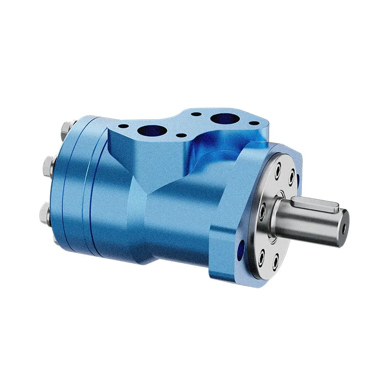
Only when the applicable motor and assembly documentation permits the actual radial, axial, bending, and weight loads. Otherwise provide the designed separate support and coupling. A product photograph cannot establish those load limits.
What should be recorded for a batch that cannot restart?
Record the material state, pause duration, temperature, attempted speed, and safely obtained supply and return pressures. Secure the equipment and follow the approved recovery procedure. Do not keep increasing pressure or repeatedly attempting a jammed start.
Recursos relacionados de produto e engenharia
Motor Orbital Hidráulico BMT, faixa de produtos de motor hidráulico, Motor Hidráulico para Sementes: Picos de Torque e Proteção contra Sobrecarga, Motor–Gearbox Spline Wear: Lubrication and Fretting at the Interface. Confirme o código completo do produto e os requisitos da aplicação ao solicitar uma revisão de configuração.
Referências técnicas
- NPTEL: agitation power requirement and dimensionless groups
- NPTEL: hydraulic motor torque, speed and efficiency exercises
- NIOSH: hazardous-energy control and stored energy
Aprendizagem adicional: motores hidráulicos
6.4 – Hydraulic Motors by NPTEL-NOC IITM provides background on motor operating principles. Motor torque, flow and efficiency relationships support the hydraulic sizing calculation. Mixing-load and restart requirements must be established separately. It supplements the component fundamentals; it is not a test procedure for the complete circuit discussed above.