Wenzhou Prance Hydraulic Equipment Co., Ltd

Hydraulic Pump Keyed-Hub Fretting: Fit, Contact and Evidence
Hydraulic pump keyed coupling fretting is damage caused by small repeated relative movements at loaded contact surfaces, often where the hub meets the shaft or key. Replacing a worn key alone may leave the cause untouched. The investigation must establish hub fit, key contact, retention, alignment and the torque duty before selecting a repair. Reddish or dark debris is a useful clue, not a complete diagnosis. Isolate the drive, control stored hydraulic energy and follow the coupling manufacturer’s removal procedure before opening the guard or disturbing the hub.
Start with the interface that is actually damaged
A keyed drive has several interfaces that can fail differently: shaft to hub bore, key to shaft keyway, key to hub keyway, flexible coupling element and the mounting structure. Damage in one location does not prove that every other interface is acceptable. Preserve photographs and component orientation before cleaning. Mark the axial position and note whether the debris is concentrated at an edge, around the bore or along one side of the key.
Fretting involves small cyclic movement under contact load. It differs from a single overload that shears a key and from continuous gross slipping that scores a shaft around its circumference. These mechanisms can coexist after a joint deteriorates. Color alone does not identify the initiating mechanism; contamination and corrosion can create similar appearances. Use the surface pattern, dimensions and operating history together.
EPRI’s maintenance guide connects loose or incorrect coupling fits with fretting and discusses hub contact, key fitting and installation. The rotational power relationship used below is supported by OpenStax’s mechanics treatment. These are general mechanical references, not tolerances or repair approvals for a Prance pump. Obtain the actual coupling drawing before deciding whether an interface is acceptable.
Why a new key may not stop the movement
The key participates in transmitting torque, but the complete joint design determines how the bore, key and retention work together. A clearance-fit keyed hub, an interference-fit assembly and a tapered arrangement do not use identical installation rules. Do not assume that a tighter bore or greater key height is always safer. A key that interferes incorrectly can prevent proper seating or impose damaging stress on the hub.
If a worn hub rocks on the shaft, replacing only the key can restore apparent engagement while allowing the damaging motion to continue. Conversely, a hub may fit correctly while an incorrect key leaves poor contact or excessive movement at the sides. Measure both components and compare them with their own specified tolerances. A replacement key selected only by approximate width is not enough.
Check axial retention separately. A set screw, clamp, shoulder, nut or other device has a defined role in the chosen coupling. Tightening an accessible screw harder cannot compensate for a damaged bore, wrong key or incorrect assembly position. Do not add improvised screws, drill a shaft or apply an unapproved retaining compound as a substitute for an engineering decision.
Distinguish fit problems from alignment and structural movement
A flexible coupling accommodates a specified amount and type of displacement; it does not eliminate the need for alignment. Misalignment can introduce repeating forces and movement at a keyed joint. Check the pump and driver according to the coupling instructions, including angular and offset alignment. Record mounting condition and coupling position so that a later comparison is meaningful.
Inspect the base, fasteners and mounting faces before interpreting alignment readings. A machine can appear aligned while loose or distorted supports allow it to move under load. Soft foot, pipe strain or an unsupported accessory can shift the assembly as bolts are tightened. Correct the installation problem using an approved procedure rather than forcing the coupling to accommodate it.
Cold alignment alone may not describe operating alignment if the driver and pump move differently with temperature. Where thermal movement is relevant, use the equipment supplier’s alignment targets and verification method. Do not invent a universal hot-alignment offset. The correct target depends on the complete assembly, its supports and operating temperature distribution.
Review torque duty before blaming the replacement part
The hydraulic demand creates a changing torque requirement at the pump shaft. Starting, pressure changes, reversal of the drive where permitted, and torsional excitation can produce a duty different from a steady average. A coupling selected only from normal running power may be unsuitable for those events. Review the applicable service factors and peak-load method with the coupling supplier.
For a steady rotating shaft, T = 9550 P/n gives torque in newton metres when P is shaft power in kilowatts and n is speed in revolutions per minute. For an illustrative shaft input of 15 kW at 1500 rpm, torque is approximately 95.5 N·m. These are assumed values, not Prance ratings. The equation does not establish peak starting torque, fatigue capacity or an acceptable key size.
If only hydraulic output power is known, do not silently substitute it for shaft input power. Losses mean the required input is different, and actual efficiency depends on operating conditions. Similarly, a motor nameplate power does not necessarily equal the pump’s measured running load. Use the appropriate duty evidence and supplier selection method rather than stacking uncertain assumptions into a precise-looking key calculation.
Inspect and measure without destroying the evidence
Remove the coupling only after electrical, mechanical and hydraulic isolation has been established and verified. Account for accumulators, suspended loads and residual pressure. Follow the specified puller, heating or hydraulic removal procedure where applicable. Hammering the hub along the pump shaft can damage bearings and obscure the original condition. Heating requires a controlled procedure compatible with nearby seals and materials.
Before cleaning, photograph deposits and witness marks. After approved cleaning, inspect the bore, shaft, key and both keyways for wear, deformation and cracking. Use suitable measuring tools at several positions to distinguish a local damaged area from an apparently acceptable average diameter. Record the measurement locations; a single caliper reading cannot establish bore roundness or the complete fit.
Where a crack or serious deformation is suspected, stop the return-to-service decision and obtain competent assessment. Polishing away evidence to make the part assemble smoothly can conceal damage and alter the required fit. The inspection result should identify which parts remain within their documented acceptance criteria and which require replacement or an approved repair.
Use the damage pattern to choose the next check
This table is a diagnostic aid, not a tolerance chart. Multiple causes can produce similar patterns. The EPRI maintenance reference supports the general fit and installation concerns; final acceptance remains specific to the actual assembly.
| Descoberta | Plausible concern | Check before deciding a repair |
|---|---|---|
| Fretting around the shaft-to-bore contact | Relative movement or unsuitable fit | Bore and shaft dimensions, retention and specified joint type |
| Heavy marking on one key flank | Uneven contact or changing torque direction | Key dimensions, keyway condition and duty history |
| Damage concentrated near one hub edge | Rocking, seating or alignment issue | Full engagement, shaft condition and alignment |
| Deformed key with hub damage | Overload or incorrect key contact | Load events, key height and coupling drawing |
| Rapid recurrence after key replacement | Root cause remains | Inspect the complete joint and mounting structure |
| New symptoms after mounting work | cURL Too many subrequests by single Worker invocation. To configure this limit, refer to https://developers.cloudflare.com/workers/wrangler/configuration/#limits | cURL Too many subrequests by single Worker invocation. To configure this limit, refer to https://developers.cloudflare.com/workers/wrangler/configuration/#limits |
cURL Too many subrequests by single Worker invocation. To configure this limit, refer to https://developers.cloudflare.com/workers/wrangler/configuration/#limits.
cURL Too many subrequests by single Worker invocation. To configure this limit, refer to https://developers.cloudflare.com/workers/wrangler/configuration/#limits
cURL Too many subrequests by single Worker invocation. To configure this limit, refer to https://developers.cloudflare.com/workers/wrangler/configuration/#limits.
cURL Too many subrequests by single Worker invocation. To configure this limit, refer to https://developers.cloudflare.com/workers/wrangler/configuration/#limits.
cURL Too many subrequests by single Worker invocation. To configure this limit, refer to https://developers.cloudflare.com/workers/wrangler/configuration/#limits.

cURL Too many subrequests by single Worker invocation. To configure this limit, refer to https://developers.cloudflare.com/workers/wrangler/configuration/#limits
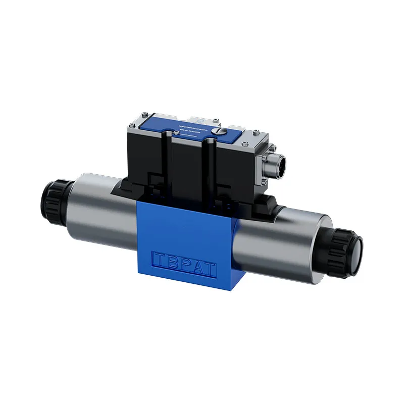
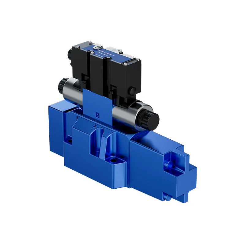
The Prance A10VO 32-series page provides a related hydraulic pump family for replacement enquiries. The original photographs illustrate that catalog product; they are not a declaration that every order has a keyed shaft. Confirm the full shaft option and drawing before choosing a hub, key or coupling. A spline option requires a different interface assessment and should not inherit keyed-hub repair instructions.
Send the complete pump and driver codes, shaft drawings, coupling identification, measured interface dimensions, damage photographs and operating duty. Identify any recent hub, motor, mounting or pressure-control changes. Ask for the compatible assembly and installation requirements together. A photo of the outside housing cannot prove the shaft tolerance, key material, engagement requirement or allowable external shaft load.

Perguntas frequentes
Does red powder prove that the key is too soft?
No. Powder can be consistent with fretting or corrosion, but it does not establish key hardness or the initiating cause. Inspect the mating surfaces, dimensions, contact pattern and duty before deciding on material changes.
Can I fit an oversized key to remove the looseness?
Only if an approved repair drawing explicitly requires it. An improvised key can prevent proper hub seating or overload the hub. The shaft, bore and keyways must meet a compatible documented design.
Should every keyed pump coupling be lubricated?
No universal lubrication rule applies. The coupling type and joint design determine surface preparation. Use the specified lubricant or dry condition; an unapproved compound can change the joint’s friction and retention behavior.
Is alignment acceptable if the flexible insert installs easily?
No. Ease of assembly does not measure angular or offset alignment under the specified conditions. Verify the mounting and alignment using the coupling manufacturer’s procedure and applicable operating targets.
Can the same hub be reused after visible fretting is cleaned off?
Only after inspection confirms that it meets the documented acceptance criteria and has no disqualifying damage. Cleaning does not restore lost dimensions or fatigue strength. Replace or repair through an approved process where the criteria are not met.
Recursos relacionados de produto e engenharia
Bomba de Pistões Variáveis Industrial A10VO Série 32, faixa de produtos de bombas hidráulicas, Que registos de instalação são importantes antes de uma revisão do acoplamento de uma bomba?, Excentricidade do Veio da Bomba Hidráulica: Medição, Limites e Desgaste do Retentor. Confirme o código completo do produto e os requisitos da aplicação ao solicitar uma revisão de configuração.
Referências técnicas
- EPRI: Flexible Shaft Couplings Maintenance Guide
- OpenStax: Work and Power for Rotational Motion
- NIOSH: Preventing Deaths from Uncontrolled Hazardous Energy
Aprendizagem adicional: bombas hidráulicas
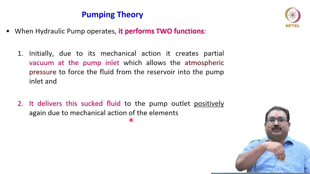
3.2 – Hydraulic Pumps by NPTEL-NOC IITM provides background on pump operating principles. The hydraulic pump lecture explains the driven component; it does not demonstrate keyed-hub installation or a Prance coupling fit. It supplements the component fundamentals; it is not a test procedure for the complete circuit discussed above.