Wenzhou Prance Hydraulic Equipment Co., Ltd

Hydraulic Pump Mounting Orientation: Case Filling, Drains, and Inlet Position
Hydraulic pump mounting orientation must be approved for the exact pump and installation. A flange that physically fits in a different position does not prove that case filling, drainage, inlet conditions, lubrication, controls, and mechanical support remain correct. Start with the applicable installation drawing and instructions, then check how gravity and the proposed plumbing affect the complete operating arrangement. Do not treat a catalog photograph, an unused threaded opening, or the orientation of a previous pump as authorization to rotate a different unit.
This guide explains the engineering review behind orientation. It does not provide a universal list of permitted shaft positions or replace the component’s filling, drain, fastening, and startup instructions.
Define the position with a drawing rather than a description
Words such as horizontal, vertical, upright, or inverted can be ambiguous when the observer, shaft direction, and machine reference are not stated. Show the shaft axis, mounting face, main hydraulic connections, relevant case connections, reservoir relationship, and gravity direction on a controlled installation drawing.
Include the pump’s complete configuration and the machine position in which it will operate. Mobile equipment may experience slope or movement that is not represented by the workshop assembly position. The review should distinguish the fixed mounting orientation from the range of actual operating attitudes. If the product instructions limit either, the installation must be checked against that limitation rather than judged from whether it can be assembled on the mounting face.
Separate mounting compatibility from operating suitability
Flange pattern, pilot fit, shaft coupling, and available space establish important mechanical interfaces. They do not prove that the hydraulic arrangement will remain suitable when the body is rotated. A different connection position may create an unfavorable hose route, make filling difficult, or put an important service point out of reach.
Keep the mechanical and hydraulic questions separate in the review. First establish that the exact assembly can be mounted and supported as intended. Then establish that its fluid conditions and auxiliary connections meet the relevant instructions. Finally check access for installation, inspection, and safe service. Passing one of these reviews should not silently stand in for all the others.
Understand why case condition matters
Some pump designs require a defined case-fluid condition for their internal components. The correct method depends on the design and operating arrangement. Do not assume that oil arriving at the main inlet automatically establishes every required condition inside the housing before rotation begins.
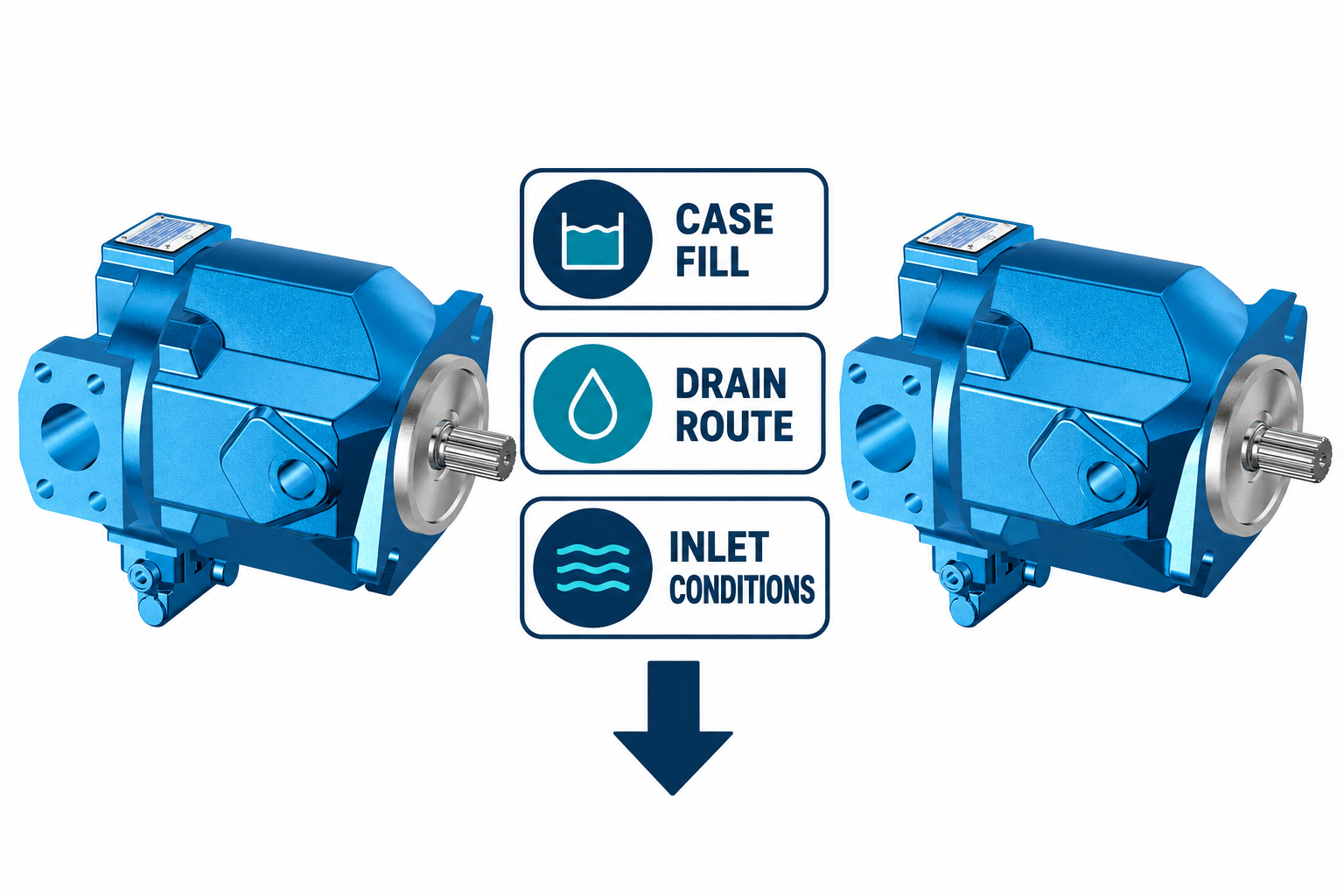
The applicable instructions should identify whether pre-filling is required, which connection or method is used, what fluid is suitable, and which checks confirm readiness. They may also address installation relative to the reservoir and drain arrangement. This article does not infer those requirements for the pictured catalog pump from its exterior. Its real product image illustrates the type of component being reviewed, not a verified cutaway or a model-specific filling diagram.
Check drain function without guessing from port position
A connection located higher on a housing may look like a convenient drain or vent, but appearance is not a port-function specification. Confirm each connection from the documentation. Where case drainage is required, evaluate the route, pressure conditions, connection arrangement, and the effect of gravity under the proposed installation.
Changing orientation can change where fluid collects or how a hose must travel. A high loop, trapped section, restricted fitting, or connection to another circuit can introduce a condition that was not present in the previous layout. Do not cure a routing problem by connecting the line to an unverified return point. Use the exact drain requirements and confirm the installed condition with the appropriate measurements and inspection.
Reassess the inlet as part of the orientation change
Moving the pump or rotating its body can change inlet routing, connection elevation, bends, service access, and the relationship to the reservoir. The inlet review should cover the actual fluid, temperature range, speed, plumbing, and operating attitudes. A short hose is not automatically a suitable hose, and a large visible port does not establish which connection is the inlet.
Keep inlet pressure conditions and case pressure conditions distinct. They describe different parts of the installation and may require separate checks. Do not use a permitted outlet pressure as a proxy for acceptable inlet vacuum. If the proposed position creates a high point or another feature that complicates the approved filling or priming process, resolve it in the design review before installation.
Use an orientation review matrix
| Review area | Prova para obter | Question to resolve before installation |
|---|---|---|
| Identity and position | Complete pump code and controlled drawing | Is this exact orientation permitted for this assembly? |
| Case preparation | Applicable filling and preparation instruction | How is the required housing-fluid condition established? |
| Drainage | Port identification and approved route | Will the route meet requirements throughout actual operating attitudes? |
| Entrada | Reservoir relationship, fluid conditions, and piping review | Are inlet conditions acceptable during startup and normal duty? |
| Mechanical support | Mounting, coupling, loads, and support drawing | Can the unit be secured without harmful imposed loading? |
| Access and release | Service space and commissioning procedure | Can necessary checks be completed safely and recorded? |
This qualitative matrix identifies review topics. It is not a list of approved mounting positions or a source of numerical limits.
Keep controls and auxiliary connections in the review
A pump may have pressure controls, displacement controls, sensing connections, or electrical equipment whose arrangement changes the space and routing requirements. A body position that clears one bracket may interfere with an adjustment, connector, or required hose. Include these features in the actual configuration rather than checking a simplified outline of the basic housing.
Confirm any limitations or preparation requirements in the relevant instructions. Do not assume that an accessory can be rotated or relocated independently because it is attached by bolts. Such a change may alter sealing, control passages, identification, or approved adjustment. Where a different option is needed for the available space, obtain a confirmed configuration instead of modifying an unfamiliar assembly to fit.
Review shaft support and coupling separately
The mounting arrangement must transmit the intended torque without imposing unacceptable mechanical loads. Alignment, support stiffness, coupling arrangement, and external loads still matter even when the hydraulic orientation is approved. A change that adds a spacer, bracket, or different coupling can change the mechanical problem.
Use the exact mounting and drive instructions, including the required fastening and alignment criteria. Do not use pipework as a structural support or force a coupling into place to overcome misalignment. The motor or engine driving the pump should not be used to pull a mispositioned assembly into alignment. Identify who checks the final installed condition and retain the results with the orientation drawing.

Plan how the pump will be filled, inspected, and serviced
An installation can be theoretically permitted but impractical to prepare or inspect safely. Check that the required filling point, drain connection, fasteners, connectors, and identification remain accessible after all guards and neighboring components are fitted. Consider the tools and controlled handling required for removal as well as the initial assembly.
A service instruction should not depend on an operator loosening an unidentified pressurized connection to determine whether fluid is present. Establish the approved inspection method during planning. Where access requires a different bracket, hose route, or configuration, resolve it before commissioning rather than leaving the installer to improvise around a space constraint.
Verify the installation through a controlled startup
Before startup, confirm identity, permitted orientation, mounting and coupling, required preparation, port functions, drain routing, and inlet arrangement. Work under the machine’s energy-control procedure and address stored energy or supported loads. Make the pre-start record specific enough that another reviewer can see what was checked rather than relying on a general “installation complete” signature.
Use the approved startup procedure and define the observations that require stopping. Record the relevant operating conditions and compare behavior through the required stages. An acceptable unloaded run does not automatically prove performance at the full temperature range, speed, or machine attitude. Complete the agreed commissioning coverage and retain any limitations, so future maintenance does not mistake a partial check for broad approval of every possible mounting position.
Perguntas frequentes
Can a hydraulic pump be mounted vertically?
Some configurations may permit particular vertical arrangements, while others have conditions or restrictions. Obtain the instructions for the exact unit and review case preparation, drainage, inlet conditions, and mechanical support. Do not infer permission from the flange alone.
Does the uppermost housing opening always become the drain?
No. Confirm connection functions and the permitted arrangement from the approved documentation. An opening’s apparent position does not establish whether it is a drain, a test connection, an auxiliary passage, or another feature.
Is mounting below the reservoir automatically sufficient?
No. Reservoir position is only one part of the installation. Fluid condition, piping, port identity, filling, drains, and operating duty still require review. A favorable elevation cannot compensate for an incorrect connection or a restricted line.
Can the pump be rotated after its hoses are connected?
Do not make that change casually. It can impose loads, change routing, or invalidate the approved arrangement. Isolate and plan the work under the applicable procedure, then recheck the mechanical and hydraulic conditions affected by the change.
What is the most useful drawing to send with an enquiry?
Send the complete pump identity and a drawing showing shaft axis, mounting face, gravity, reservoir relationship, hydraulic connections, available space, and actual machine operating attitudes. Include the relevant duty and fluid conditions so the response can address the real installation.
Produtos e recursos de engenharia relacionados
The Variable Displacement Pump OEM A10VO 31 Series catalog exterior is used as the real product reference in these explanatory images. It does not establish the approved service method, optional construction, or operating limits for an individual order. Confirm the complete code and its documentation. Related resources: Bomba de Deslocamento Variável OEM Série A10VO 31, gama de bombas hidráulicas, Flanges de Montagem de Bombas Hidráulicas: SAE de Dois Furos vs Quatro Furos, Guia de Dimensionamento e Encaminhamento da Linha de Drenagem da Caixa da Bomba Hidráulica, Condições de Entrada da Bomba Hidráulica: Uma Lista de Verificação para o Comprador Antes de Encomendar.
Sources and limits of this guide
The university resource supports the component operating principles. NIOSH supplies hazardous-energy prevention context; exact machine isolation and component service requirements still need their approved procedures. ISO references identify the stated standard scope. This guide does not reproduce paid clauses or turn their abstract into model-specific limits.
- NPTEL: Fundamentos de Hidráulica e Pneumática Industrial
- NIOSH: prevenção de lesões causadas por energia perigosa
- DIN Media: DIN EN ISO 4413, hydraulic fluid power general rules and safety requirements (standard overview)
University lesson: operating principles
NPTEL IIT Guwahati presents Lec 31: Flow control and pressure relief valves. The lesson supports the pump operating principles used in the engineering discussion; it is not a model-specific repair, storage, or installation approval.