Wenzhou Prance Hydraulic Equipment Co., Ltd

Hydraulic Solenoid Suppression Diodes: Polarity and Release Time
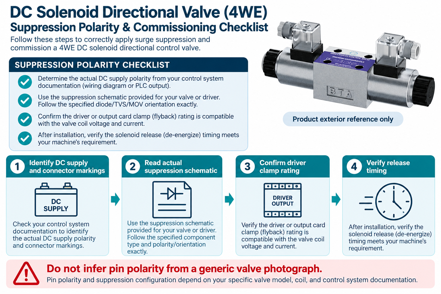
A suppression diode across a DC hydraulic solenoid coil normally remains reverse biased while the coil is energized, then provides a path for inductive current after the driver switches off. In the simple conventional arrangement, its cathode faces the coil terminal that is positive during energization. This is a circuit principle, not a universal connector pin assignment. Confirm the actual coil, connector, suppression device, and output-driver documentation before connecting anything. A reversed or incompatible device can produce an electrical fault, while a correctly connected flyback diode can still change how quickly the valve releases.
The key purchasing and engineering question is therefore not merely whether the connector contains a diode. It is whether the complete suppression arrangement protects the electrical output and still allows the machine to reach its required hydraulic state at the required time.
Why current continues after switch-off
A coil stores energy in its magnetic field. Changing its current requires a voltage associated with its inductance, commonly expressed as v = L × di/dt for the inductive part of a simplified model. Interrupting the supply does not make that stored energy disappear. Without an appropriate discharge path, the resulting transient can stress the switching device and surrounding circuit.
The stored magnetic energy in a simplified linear-inductance model is E = ½ × L × I². Actual solenoid inductance can vary with armature position and operating condition, so this relationship is an explanation rather than a component-selection calculation for an unknown valve. The driver and suppression arrangement must be evaluated for the actual repetitive switching duty, including energy handling and temperature, rather than selected only from the nominal supply voltage.
Understand what the diode does during normal energization
In a conventional diode placed across a DC coil, the orientation prevents substantial forward conduction through the diode while the intended supply is applied. The coil can then develop its normal electromagnetic force. If that diode is reversed relative to the applied polarity, the circuit may present a low-resistance path that the controller or protection system must respond to.
Do not intentionally reverse a supply to discover the correct orientation. Identify the approved schematic, terminal markings, connector arrangement, and output topology first. A bare coil, a diode-equipped connector, a rectifier-equipped connector, and an electronically controlled assembly can behave differently. Similar external connector shapes do not establish which internal circuit is present or which terminal should receive a particular conductor.
Follow the current path after the driver opens
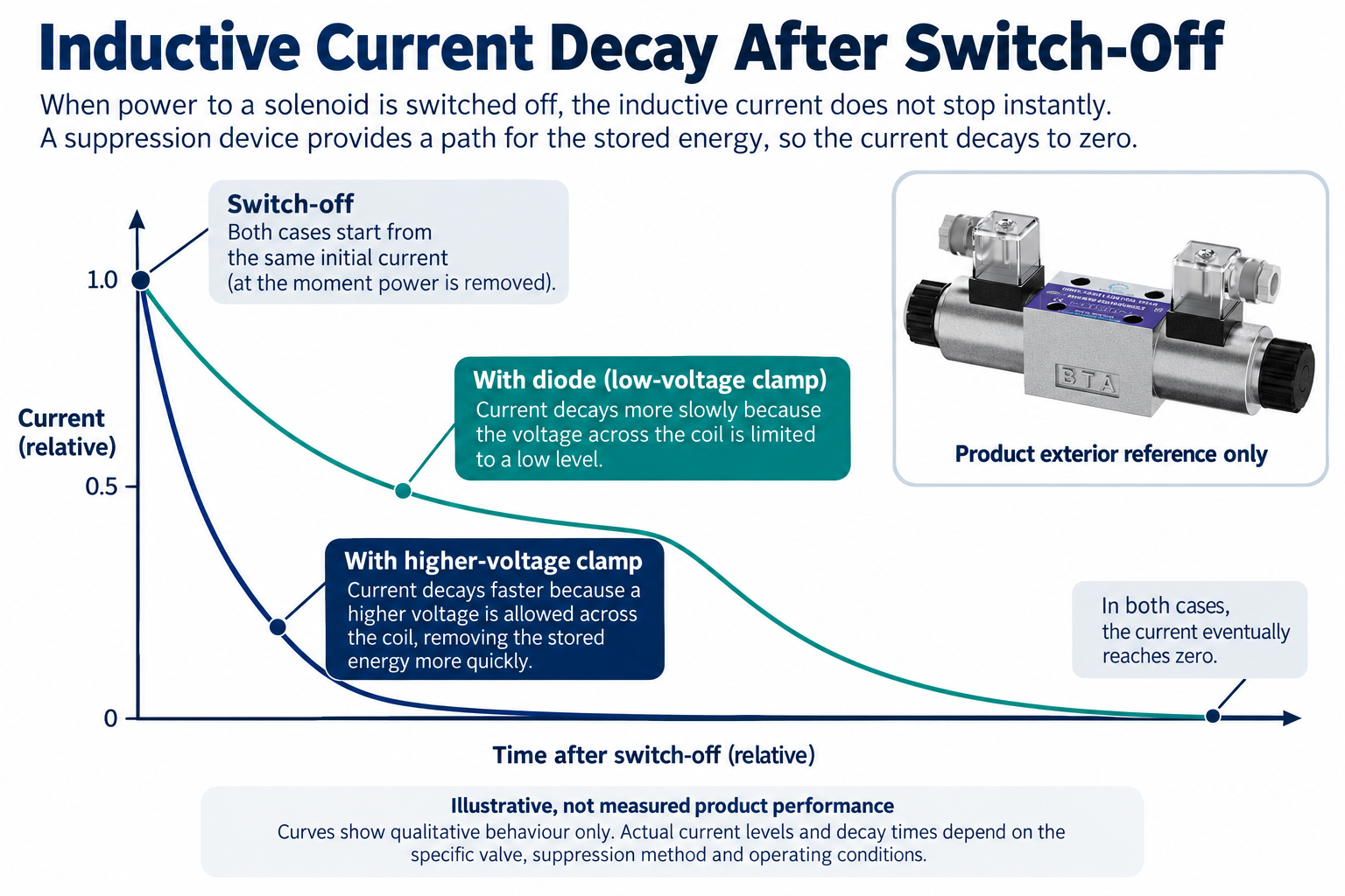
When the supply path opens, the coil current tends to continue in its previous direction. A flyback diode can allow current to circulate through the coil and diode while the stored energy is dissipated. In comparison with a suitable higher-voltage clamp, the relatively low clamp voltage generally permits a slower current decay.
This is why suppression can influence release behavior even when steady energized current appears normal. The diagrammed curves are qualitative and are not measurements for the pictured 4WE valve. They do not specify a universal time constant or guarantee the time at which the spool reaches a particular position. Circuit resistance, inductance, magnetic behavior, driver topology, and the mechanical valve assembly all contribute to the actual result.
Compare suppression choices without treating them as interchangeable
| Arranjo | Useful principle | Checks required for the actual installation |
|---|---|---|
| Conventional flyback diode | Provides a low-voltage recirculating path after DC switch-off | Polarity, repetitive current and energy duty, and acceptable release behavior |
| Higher-voltage clamp or suitable TVS arrangement | Allows a different voltage during discharge and can shorten current decay | Driver voltage capability, clamp characteristics, energy rating, and complete topology |
| Suppression integrated into the output driver | Discharge behavior is part of the controller design | Manufacturer instructions on external components and allowable load |
| Connector with built-in electronics | Electrical behavior may include more than a bare diode | Exact circuit, supply requirements, pinout, and compatibility |
| Unidentified accessory or replacement connector | Function cannot be inferred from its housing | Obtain identification before energizing or substituting |
The table is a conceptual comparison. It does not recommend a specific diode, TVS voltage, driver, or connection for every hydraulic solenoid.
Keep current decay separate from hydraulic release time
Electrical current decay is only one part of a valve’s transition after switch-off. Magnetic force, armature movement, spring action, spool movement, pressure forces, friction, and the connected circuit can affect the useful hydraulic response. A faster electrical decay does not by itself prove that the actuator reaches a safe or required state sooner under every condition.
Define which event matters to the machine: loss of coil current, movement of the valve element, change in a hydraulic passage, stopping of an actuator, or establishment of a holding condition. These events are not identical. A timing claim should identify the measured event and operating conditions. Do not use an oscilloscope trace of an unloaded coil as complete validation of the machine’s hydraulic stopping behavior.
Review the controller before adding an external device
The output may already include an active clamp or another suppression strategy. Adding a diode without reviewing the controller can alter discharge behavior or conflict with the intended diagnostic and switching functions. A controller’s nominal output current does not describe every transient, energy, or repetitive switching limit.
Obtain the output documentation and the coil information together. Identify supply range, load current, switching duty, permitted inductive energy, clamp behavior, and any restrictions on external suppression. Where the documentation does not resolve compatibility, seek confirmation from the responsible equipment or component provider. Do not treat a successfully illuminated connector indicator as proof that the entire output stage is protected under turn-off conditions.
Identify the connector as a functional part
A connector can contain a light, diode, rectifier, suppressor, or another circuit. The exact accessory code matters. A replacement that fits mechanically and carries the same apparent voltage marking may still alter polarity sensitivity or release behavior. Keep the connector and coil references together in the service record.
Use an approved schematic and appropriate de-energized checks when identifying an assembly. Semiconductor paths can affect meter readings, including differences when the probes are reversed. These observations should not be interpreted as proof of winding damage without considering the internal circuit. Avoid applying an unapproved high-voltage insulation test to an accessory or electronic assembly; the permitted method and test boundary must be established first.
Do not transfer the simple DC rule to every supply arrangement
A single flyback diode across a conventional DC coil is not a generic solution for AC coils, rectified assemblies, or all switching topologies. A bidirectional clamp, a unidirectional device, and a connector containing a bridge have different circuit behavior. Their labels cannot be reduced to a shared instruction to connect any suppressor across any two pins.
This guide deliberately does not supply a universal pin-number diagram for the real valve photograph. The photograph establishes an exterior product reference, not its fitted accessory circuit. Confirm the complete ordered configuration and the actual machine wiring. If a service change replaces the original suppression method, evaluate it as a change to electrical and hydraulic behavior rather than assuming the accessory is functionally invisible.
Verify the result under the relevant duty
Plan testing with competent personnel, suitable instrumentation, and the machine’s isolation and movement-control procedures. Electrical and hydraulic stored energy must be considered together. Define safe test conditions, the measured events, and the observations that require stopping before energization begins.
Where appropriate, verify coil current and transient behavior with equipment suitable for the circuit, then evaluate the required valve and machine response under the approved commissioning procedure. Include relevant supply, temperature, pressure, and switching conditions. A successful single operation at room temperature is not the same as demonstrated behavior through the intended repetitive duty. Record the accessory, controller configuration, and test boundary so the result remains understandable after future maintenance.
Keep purchasing specifications explicit
Specify the coil and connector codes, electrical supply and driver, existing suppression method, relevant switching duty, and required release behavior. Ask whether a proposed substitute changes polarity requirements, discharge characteristics, diagnostic behavior, or the test needed before release. A low-cost connector substitution can have a wider effect than its physical size suggests.
Store the approved wiring and functional test record against the actual valve assembly. If a technician later replaces a connector or output module, those records provide a basis for comparing the new arrangement rather than rediscovering it by trial. The result should be a compatible, traceable circuit with verified behavior, not merely a valve that happens to energize after a service intervention.
Perguntas frequentes
Which way does a basic flyback diode face across a DC coil?
In the conventional simple circuit, it is reverse biased during energization, with the cathode toward the coil terminal that is positive then. Confirm the actual schematic and terminal identification; this principle does not establish universal connector pin numbers.
Can suppression make a valve release more slowly?
It can affect the electrical current decay. A low-voltage flyback path generally permits slower decay than a compatible higher-voltage clamp. Actual valve and machine timing also depend on mechanical and hydraulic conditions and require the relevant verification.
Is a higher-voltage clamp always better?
No. Its voltage, energy handling, topology, driver compatibility, and resulting response must be appropriate. Faster current decay is not permission to exceed an output’s limits or a complete demonstration of machine stopping performance.
Can I fit a diode connector to any coil with the same voltage?
Not safely on that information alone. Confirm the exact coil, supply type, connector circuit, polarity, controller, and switching requirements. Mechanical fit and a matching voltage label do not establish complete compatibility.
What should be recorded after a connector change?
Retain the exact accessory and coil identities, approved circuit, controller arrangement, compatibility confirmation, and the electrical and functional checks performed. Record any limits of the test instead of describing a partial check as complete validation.
Produtos e recursos de engenharia relacionados
The Directional Valve 4WE catalog exterior is used as the real product reference in these explanatory images. It does not establish the approved service method, optional construction, or operating limits for an individual order. Confirm the complete code and its documentation. Related resources: Válvula Direcional 4WE, gama de bombas hidráulicas, Bobinas de Solenoide Hidráulico AC vs DC: Fornecimento, Início de Circuito e Substituição, Teste de resistência da bobina do solenóide hidráulico: Ohms e temperatura, Tempo de resposta da válvula hidráulica: medição e fatores que influenciam.
Sources and limits of this guide
The university resource supports the component operating principles. NIOSH supplies hazardous-energy prevention context; exact machine isolation and component service requirements still need their approved procedures. The technical sources support general operating principles; the pictured catalog exterior does not establish model-specific limits or optional features.
- Texas Instruments: inductive-load discharge and clamping
- Texas Instruments: solenoid current control and decay
- NIOSH: prevenção de lesões causadas por energia perigosa
University lesson: directional-valve switching
NPTEL-NOC IITM presents 5.1 – Directional Control Valves. This lesson explains the directional valve and switching function behind the discussion of hydraulic release. Electrical suppression, polarity, and driver compatibility require the technical sources and exact component documentation above; the video is not a connection approval.