Wenzhou Prance Hydraulic Equipment Co., Ltd

")
")
")
")
")
")
Fixed Displacement Motor A2F
1.Fixed displacement motor A2FM of axial piston , bent axis design,suitable for hydrostatic drives in open and closed circuits.
2.Use in mobile and industrial applications
3.The output speed depends on the flow capacity of the pump and the displacement of the motor
4The torque increases with the pressure different between the high and low pressure side and with increasing displacement
5.Careful selection of the displacement offered ,permit sizes to be matched to practically every application
6.One piece pistons with piston rings
Detailed description
The A2FM is a fixed displacement motor featuring an axial piston, bent axis design, specifically engineered to be suitable for hydrostatic drives in both open and closed circuits. Its bent axis structure optimizes power transmission efficiency, reduces internal mechanical wear, and ensures stable operation in different circuit systems, meeting the diverse needs of hydraulic drive applications. This motor is widely applicable to both mobile and industrial scenarios, including construction machinery, agricultural equipment, industrial hydraulic stations, and other equipment requiring reliable hydraulic power, adapting well to harsh mobile working environments and stable industrial operation conditions. The output speed of the A2FM motor depends on the flow capacity of the matching pump and the motor’s own displacement—higher pump flow or smaller motor displacement leads to higher output speed, allowing flexible adaptation to different speed requirements. Its torque increases with the pressure difference between the high and low pressure sides, as well as with increasing displacement, ensuring sufficient power to drive heavy loads stably. A careful selection of the available displacement options allows the motor sizes to be precisely matched to practically every application, enhancing versatility. Additionally, it adopts one-piece pistons with piston rings, which improves sealing performance, reduces internal leakage, and enhances the motor’s durability and operational reliability.
Technical Data
Hydraulic fluid
The A2FM fixed displacement motor is suitable for use with mineral oil.
Viscosity range
We recommend that a viscosity (at operating temperature)for optimum
efficiency and service life purposes of
Vopt= optimum viscosity 16...36mm2/s
Be chosen, taken the circulation temperature (closed circuit) and tank temperature (open circuit) into account.
Limits of viscosity range
The following values apply extreme cases:
Vmin=5mm2/s
short term(t < 3 min) at max. permitted temperature
tmax=115℃
Vmax=1600mm2/s
short term (t<3 min) with cold start(P<3MPa,
n≤1000rpm tmin=-40℃)
Note that the maximum hydraulic fluid temperature must not be exceeded locally either (e.g.bearing area).The temperature in the bearing area is-depending on pressure and speed-up to 12 K higher than the average case drain temperature.
Selection diagram
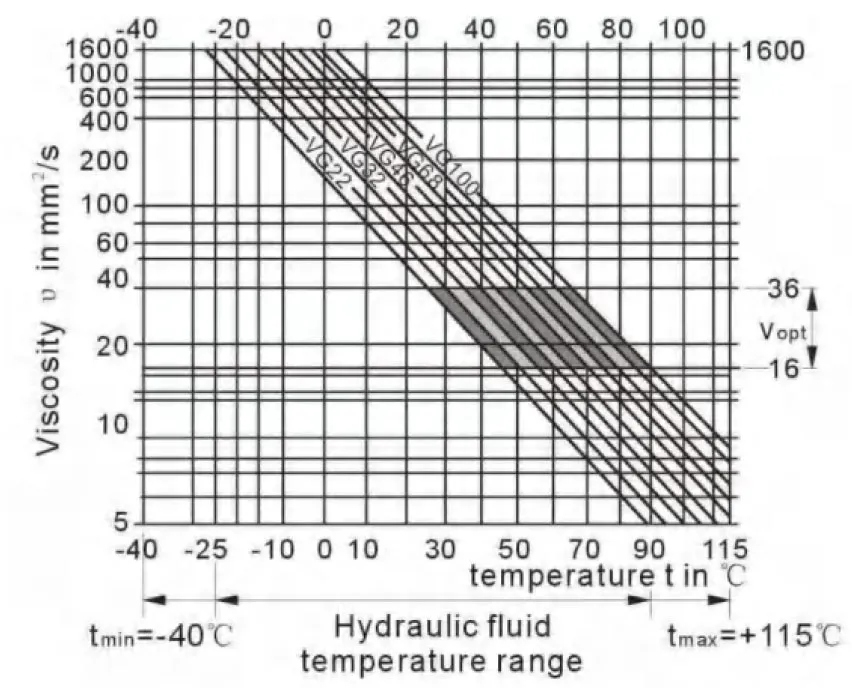
Details regarding the choice of hydraulic fluid
The correct choice of pressure fluid requires knowledge of the operating temperature in relation to the ambient temperature:in a closed circuit the circulation temperature,in an open circuit the tank temperature.
The hydraulic fluid should be selected so that within the operating temperature range,the operating viscosity lies within the optimum range (υ opt) (see shaded section of the selection diagram).We recommend that the highest possible viscosity range should be chosen in each case.
Example:At an ambient temperature of X℃ an operating temperature of 60℃ is set in the circuit . In the optimum operating viscosity range (υ opt; shaded area) this corresponds to the viscosity classes VG 46 or VG68; to be selected: CG 68
Please note : The leakage fluid temperature, which is affected by pressure and rotational speed, is always higher than the circulation temperature or tank temperature. At no point in the system may t-he temperature be higher than 115℃.
Filtration
The finer the filtration, the cleaner the fluid and the longer the service life
of the axial piston unit.
To ensure proper function of the axial piston unit, the hydraulic fluid must have a cleanliness level of least.
20/18/15 according to ISO 4406.
At very high hydraulic fluid temperatures (90℃ to max. 115℃),a cleanliness level of at least.
19/17/14 according to ISO 4406 is required.
Please contact us if these cleanliness levels cannot be achieved.
Operational pressure range
Maximum pressure on port A or B
(pressure data according to DIN 24312)
| Shaft end A,Z | Shaft end B, P | |
| Nominal pressure PN | 40 Mpa | 35 Mpa |
| Peak pressure Pmax | 45 MPa | 40 MPa |
| summation pressure (A+B) | 70 MPa | 70 MPa |
Please note:at the shaft end Z and P, a nominal pressure of PN=31. 5MPa (Pmax=35MPa) is permitted for the driven shaft end that is subjected to transverse bending (pinions, V-belts) !
Size 56 with shaft end Z:PN=35MPa, Pmax=40MPa
in cases of pulsating loading above 31. 5MPa, we recommend the version with splined shaft A or splined shaft Z(sizes 45)
Direction of flow
Speed rang
No limit to minimum speed nmin. If uniform motion is required,nmin must not be less than 50 rpm.
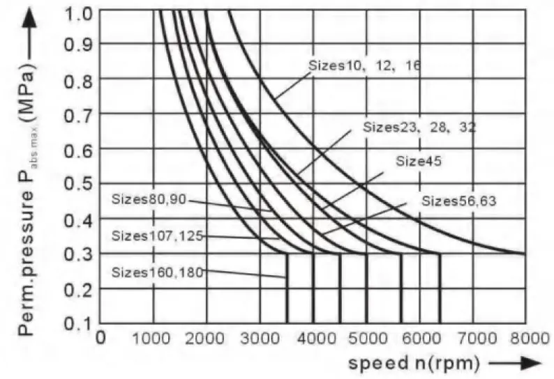
Shaft seal ring
permissible pressure load
The pressure service life of the shaft seal ring is affected by the speed of the motor and the case drain pressure. The permitted loading with intermittent case drain pressure depends on the rotational speed(see chart). Short-term (t<5 min) pressure spikes of up to 1 Mpa absolute are permitted.
The average permanent case drain pressure must not exceed 0. 3Mpa absolute.
The pressure in the case must be equal to or greater than the external pressure on the shaft seal.
Temperature range
The FKM shaft seal is admissible for a housing temperature range
from -25℃ to +115℃
Table of values (theoretical values, ignoring ηmin and ηv; values rounded)
| Size | 10 | 12 | 16 | 23 | 28 | 32 | 45 | |||
| Displacement | Vg | mL/r | 10.3 | 12.0 | 16.0 | 22.9 | 28.1 | 32 | 45.6 | |
| Speed max | nmax | min-1 | 8000 | 8000 | 8000 | 6300 | 6300 | 6300 | 5600 | |
| nmax limit1) | min-1 | 8800 | 8800 | 8800 | 6900 | 6900 | 6900 | 6200 | ||
| Flow max. | qvmax | L/min | 82 | 96 | 128 | 144 | 176 | 201 | 255 | |
| Torque constants | TK | Nm/MPa | 1.64 | 1.9 | 2.5 | 3.6 | 4.45 | 5.09 | 7.25 | |
| Torque at | Δp=35 MPa | T | Nm | 57 | 67 | 88 | 126 | 156 | 178 | 254 |
| Δp=40 MPa | T | Nm | 65 | 76 | 100 | 144 | 178 | 204 | 290 | |
| Filling capacity | L | 0.17 | 0.17 | 0.17 | 0.20 | 0.20 | 0.20 | 0.33 | ||
| Mass moment of inertia around output shaft |
J | kgm2 | 0.0004 | 0.0004 | 0.0004 | 0.0012 | 0.0012 | 0.0012 | 0.0024 | |
| Mass(approx.) | kg | 5.4 | 5.4 | 5.4 | 9.5 | 9.5 | 9.5 | 13.5 | ||
| Size | 56 | 63 | 80 | 90 | 107 | 125 | 160 | 180 | |||
| Displacement | Vg | mL/r | 56.1 | 63.0 | 80.4 | 90.0 | 106.7 | 125.0 | 160.4 | 180.0 | |
| Speed max | nmax | min-1 | 5000 | 5000 | 4500 | 4500 | 4000 | 4000 | 3600 | 3600 | |
| nmax limit1) | min-1 | 5500 | 5500 | 5000 | 5000 | 4400 | 4400 | 4000 | 4000 | ||
| Flow max. | qvmax | L/min | 280 | 315 | 360 | 405 | 427 | 500 | 577 | 648 | |
| Torque constants | TK | Nm/MPa | 8.9 | 10.0 | 12.7 | 17.0 | 19.9 | 25.4 | 28.6 | 31.8 | |
| Torque at | Δp=35 MPa | T | Nm | 312 | 350 | 445 | 501 | 595 | 697 | 889 | 1001 |
| Δp=40 MPa | T | Nm | 356 | 400 | 508 | 572 | 680 | 796 | 1016 | 1144 | |
| Filling capacity | L | 0.45 | 0.45 | 0.55 | 0.55 | 0.8 | 0.80 | 1.1 | 1.1 | ||
| Mass moment of inertia around output shaft |
J | kgm2 | 0.0042 | 0.0042 | 0.0072 | 0.0072 | 0.0116 | 0.0116 | 0.0220 | 0.0220 | |
| Mass(approx.) | kg | 18 | 18 | 23 | 23 | 32 | 32 | 45 | 45 | ||
1) intermittent maximum speed: overspeed at discharge and over-running travel operations,t<5 sec. and Δp<15MPa.
Determining the size
| Flow | qv=(Vg∙n)/(1000∙ηv) | [L/min] | Vg=Displacement per revolution in mL/r Δp=Differential pressure in MPa n=Speed in rpm ηv=Volumetric efficiency ηmh=Mechanical-hydraulic efficiency ηt=Overall efficiency |
| speed | n=(qv∙1000∙ηv)/Vg | [rpm] | |
| Torque | T=(Vg∙ Δp∙ηmh)/20π | [Nm] | |
| Power | P=(2π∙T∙n)/60000=(qv∙Δp)/(600∙ηt) | [KW] |
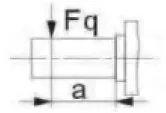
Permissible radial and axial loading on the drive shaft
The values given are maximum values and do not apply to continuous operation
| Size | 10 | 12 | 16 | 23 | 28 | 32 | 45 | 56 | |||
| Radial force,max.1) at distance a (from shaft collar) |
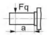 |
Fqmax | N | 2350 | 2750 | 3700 | 4300 | 5400 | 6100 | 81502) | 92002) |
| a | mm | 16 | 16 | 16 | 16 | 16 | 16 | 18 | 18 | ||
| Axial force, max.3) | 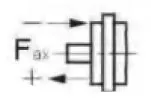 |
+Fax max | N | 320 | 320 | 320 | 500 | 500 | 500 | 630 | 800 |
| -Fax max | N | 320 | 320 | 320 | 500 | 500 | 500 | 630 | 800 | ||
| Permissible axial force/MPa operating pressure |
±Fax per/MPa | N/MPa | 30 | 30 | 30 | 52 | 52 | 52 | 70 | 87 | |
| Size | 63 | 80 | 90 | 107 | 125 | 160 | 180 | |||
| Radial force,max.1) at distance a (from shaft collar) |
 |
Fqmax | N | 10300 | 115002) | 12900 | 13600 | 15900 | 18400 | 20600 |
| a | mm | 18 | 20 | 20 | 20 | 20 | 25 | 25 | ||
| Axial force, max.3) | 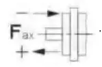 |
+Fax max | N | 800 | 1000 | 1000 | 12500 | 1250 | 1600 | 1600 |
| -Fax max | N | 800 | 1000 | 1000 | 12500 | 1250 | 1600 | 1600 | ||
| Permissible axial force/MPa operating pressure |
±Fax per/MPa | N/MPa | 87 | 106 | 106 | 129 | 129 | 167 | 167 | |
1) during intermittent operation
2)permissible max.radial force with shaft end Z:Fq max = 6500N
3)max. permissible axial force when stopped or when axial piston unit working in pressureless conditions
4)when stopped or when axial piston unit working in pressureless condition. Higher forces are permitted when under pressure.
Please contact us.
When considering the permissible axial force, the force-transfer direction must be taken into account:
-Fax max = increase in service life of bearings
+Fax max =reduction in service life of bearings(avoid if at all possible)
Minimum inlet pressure on service line port A(B)
In order to avid damage of the motor a minimum inlet pressure at the inlet zone must be assured.
The minimum inlet pressure is related to the rotational speed of the fixed motor.
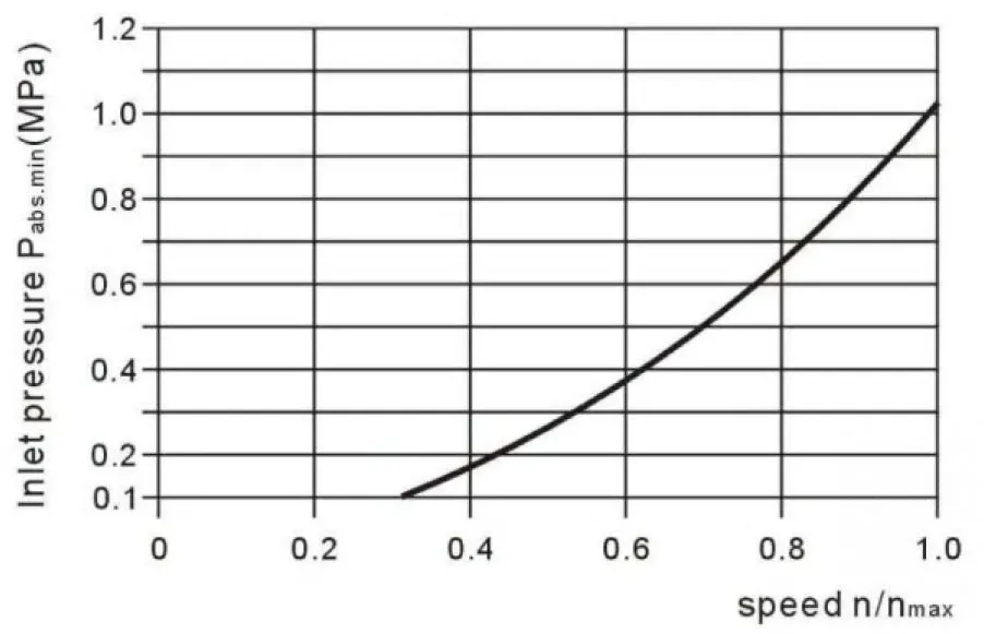
Please contact us if these conditions cannot be satisfied.