Wenzhou Prance Hydraulic Equipment Co., Ltd

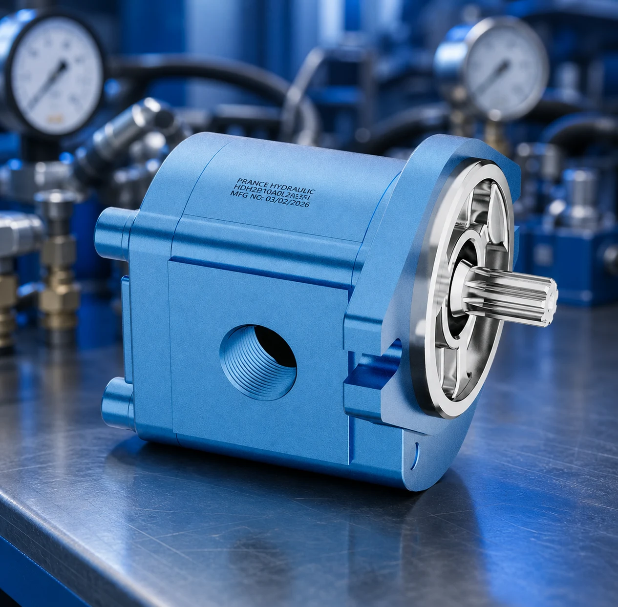
Hydraulic Cast Iron Gear Pump: Working Principle, Specs & Applications
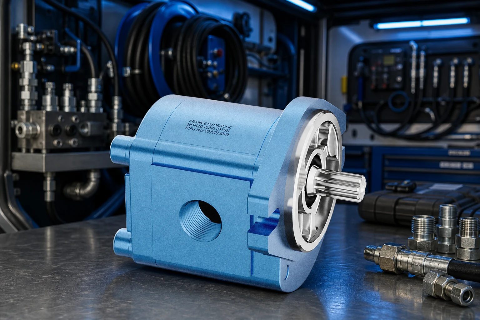
Hydraulic Cast Iron Gear pump — Cast iron hydraulic gear pumps use positive displacement gear meshing to move fluid in mobile and industrial circuits where rugged housings and moderate-to-high pressure are required. This guide focuses on hydraulic sizing, application fit, and procurement documentation for export and industrial buyers. Cross-check public data on prancehydraulic.com and confirm project limits with your design engineer.
Part 1. Core Concepts and Working Principle
This section explains how hydraulic cast iron gear pump fits in open-circuit and industrial hydraulic systems as a positive-displacement component.
Buyers should confirm displacement, rated pressure, speed limits, and fluid compatibility before comparing quotations.
Misalignment between catalog peaks and actual duty cycle is a common source of overheating, noise, and early wear.
Size displacement from required flow at actual shaft speed: Q ≈ displacement × speed × volumetric efficiency factor.
Confirm inlet conditions—line size, height, temperature, and fluid viscosity at cold start—not only steady-state catalog data.
Cross-check Prance Hydraulic product line against your circuit pressure, relief setting, and filtration plan.
For export machines, confirm port standards (SAE/ISO), rotation, and shaft type before issuing PO.
Include duty pressure, flow, fluid type, ambient temperature, and duty cycle in every RFQ.
Confirm imperial and metric port and shaft dimensions for export machines before fabrication.
Define warranty response, spare parts lead time, and who performs startup in the purchase order.
Tip: Request duty-point data sheets, not marketing summaries alone.
Part 2. Specifications, Limits, and Selection Criteria
Continuous versus intermittent pressure ratings must match your relief valve setting and load cycle.
Inlet conditions, filtration (ISO 4406), and fluid viscosity at cold start affect both performance and service life.
Mounting, shaft, rotation, and port orientation should be frozen before mechanical design sign-off.
Case drain lines on piston units must return to tank without excessive backpressure; plug unused ports per manufacturer guidance.
Parallel pump circuits need isolation and load-sharing review to avoid fighting or overheating.
Heat exchangers or tank volume may be required when duty cycle is high—do not size tank from catalog defaults alone.
Use hydraulic solutions pages for integrated system questions that span pump, valve, and motor selection.
Include duty pressure, flow, fluid type, ambient temperature, and duty cycle in every RFQ.
Confirm imperial and metric port and shaft dimensions for export machines before fabrication.
Define warranty response, spare parts lead time, and who performs startup in the purchase order.
| Parameter | What to verify | Typical source |
|---|---|---|
| Pressure / flow | Duty point vs continuous rating | Manufacturer curve |
| Speed range | Motor/pump RPM limits | Datasheet |
| Fluid / temperature | Viscosity window | O&M manual |
| Filtration | Inlet cleanliness target | ISO 4406 / OEM spec |
Important: Do not operate hydraulic pumps or motors without adequate inlet supply and relief protection—cavitation and over-pressure cause rapid wear and safety hazards.
Part 3. Field Application and Installation Notes
On site, Hydraulic Cast Iron Gear pump selection must match actual piping, tank, and relief architecture—not spreadsheet assumptions alone.
Verify rotation, mounting torque, and port orientation before first pressurization.
Inlet vacuum and return backpressure limits are common root causes of premature failure.
Document startup pressure, temperature, and case drain (if applicable) at acceptance.
After startup, log pressure, flow, case drain, and temperature at working load for baseline troubleshooting.
Seal and bearing wear often appears as noise, heat, or rising case drain before total loss of function.
Submit non-catalog duty points via Prance Hydraulic engineering contact for application review.
Keep fluid analysis on a schedule when contamination or water ingress is possible.
Include duty pressure, flow, fluid type, ambient temperature, and duty cycle in every RFQ.
Confirm imperial and metric port and shaft dimensions for export machines before fabrication.
Define warranty response, spare parts lead time, and who performs startup in the purchase order.
| Check item | Why it matters | Typical owner |
|---|---|---|
| Inlet / return line size | Prevents cavitation and overheating | Hydraulic designer |
| Relief setting vs component rating | Prevents over-pressure damage | Commissioning |
| Filtration beta ratio | Protects clearances | Maintenance |
| As-built schematic | Supports future service | Owner O&M |
Tip: Photograph nameplates and port labels during acceptance—they are required for correct spare parts.
Tip: Archive baseline pressure, flow, and temperature readings after commissioning.
Part 4. Documentation and Handover Checklist
Industrial acceptance relies on documented ratings and test evidence—not verbal assurances.
Use the tables below as a hydraulic RFQ and handover starting point; your EPC contract may require more.
Cross-check related Prance Hydraulic product pages for public specifications and request gaps in writing.
Normalize Incoterms, warranty, and commissioning scope when comparing suppliers.
| Document / item | Purpose | When to request |
|---|---|---|
| Performance / displacement curve | Verify flow at speed and pressure | Before purchase order |
| Mounting / shaft / port drawing | Mechanical and piping design | Design phase |
| Filtration and fluid spec | Prevent premature wear | Before first fill |
| Spare seal / kit list | Lifecycle planning | Contract negotiation |
| Commissioning checklist | Acceptance at duty point | Before handover |
| Application | Typical component | Selection note |
|---|---|---|
| Mobile construction auxiliaries | Gear or piston pump | Confirm pressure, speed, and tank size |
| Industrial power unit | Gear, vane, or piston pump | Match displacement to motor RPM and relief setting |
| Crane / drill rig drives | Piston motor (e.g. A6VM class) | Check case drain and speed limits |
| Wheel / conveyor drive | Orbit motor | Size displacement for torque at low speed |
| Direction / proportional control | Solenoid or proportional valve | Match flow, pressure drop, and electrical interface |
Tip: Store factory test reports with the component serial number.
Tip: Keep fluid analysis reports with the machine maintenance file.
Part 5. Commissioning, Monitoring, and Long-Term Operations
Commissioning should verify performance at working pressure and speed, not only correct rotation direction.
Log baseline pressure, temperature, case drain (if fitted), and noise at acceptance load.
Train maintenance on lockout/tagout, filter change intervals, and fluid sampling procedures.
Trend case drain and temperature in service—step changes often precede seal or bearing failure.
After circuit modifications, re-verify relief settings and hose ratings before returning to production.
Keep spare seal kits and critical filters based on lead time and downtime cost.
Tip: Re-sample fluid after the first 100 hours if the system was flushed at commissioning.
Recommended Prance Hydraulic Products
For project support, explore our related product line, solution options, and OEM/ODM capabilities on prancehydraulic.com.
FAQ
What is a cast iron hydraulic gear pump?
It is a positive-displacement pump with cast iron housing and meshing gears that move a fixed volume of hydraulic fluid each revolution.
How does a hydraulic gear pump work?
Gear teeth separate at the inlet to draw fluid in, carry it around the housing, and force it out at the outlet as teeth mesh again.
What pressure can a cast iron gear pump handle?
Many industrial and mobile cast iron designs are specified in roughly 200–300 bar (about 2900–4350 psi); confirm continuous vs peak ratings on the datasheet.
What is the difference between external and internal gear pumps?
External gear pumps use two external gears; internal designs use a crescent partition and often run quieter with good high-viscosity suction performance.
Where are cast iron gear pumps used?
Common uses include construction and agricultural auxiliaries, industrial power units, lubrication circuits, and moderate-pressure transfer lines.
How do you size a hydraulic gear pump?
Calculate required flow from displacement × shaft speed, then verify pressure rating, inlet conditions, fluid viscosity, and filtration match the duty cycle.
Why use cast iron instead of aluminum for gear pumps?
Cast iron adds rigidity and damping under cyclic pressure; aluminum may be lighter but is selected when weight matters and duty is less severe.
What filtration is required for hydraulic gear pumps?
Manufacturer literature often references ISO 4406 cleanliness around 18/16/13 at the pump inlet—finer filtration generally extends gear and bearing life.
References
- Michael Smith Engineers — Gear Pumps
- Danfoss PowerSource — Rugid cast iron gear pumps
- Danfoss XD Series datasheet
- Prance External Gear Pump HDH
Ready to discuss your project? Contact Prance Hydraulic engineering support with your project parameters and technical requirements.