Wenzhou Prance Hydraulic Equipment Co., Ltd

Internal vs External Gear Pump: Which Hydraulic Design Fits?
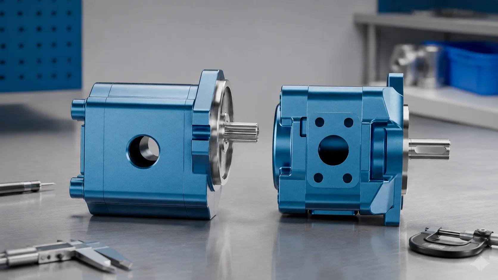
Internal gear pump vs external gear pump selection begins with geometry. An external gear pump uses two similar externally toothed gears that mesh with each other. An internal gear pump places a smaller external gear inside a larger internally toothed ring, commonly with a crescent separator between them. Both are positive-displacement rotary pumps, but their flow path, package shape, noise behavior, fluid tolerance, inlet performance, service approach, and available hydraulic designs differ. Neither layout is universally better. For a hydraulic application, compare the manufacturer’s pressure, speed, viscosity, temperature, displacement, efficiency, contamination, and mounting data at the real duty point—not broad statements borrowed from process-pump applications.
How an external gear pump moves oil
The drive gear turns an idler gear in a close-fitting housing. As teeth unmesh at the inlet, chamber volume grows and oil enters. Fluid is carried around the outside of both gears between tooth spaces and the housing. At the outlet, the gears mesh again, reducing volume and displacing oil into the pressure port. The meshing zone prevents oil from passing directly through the center.
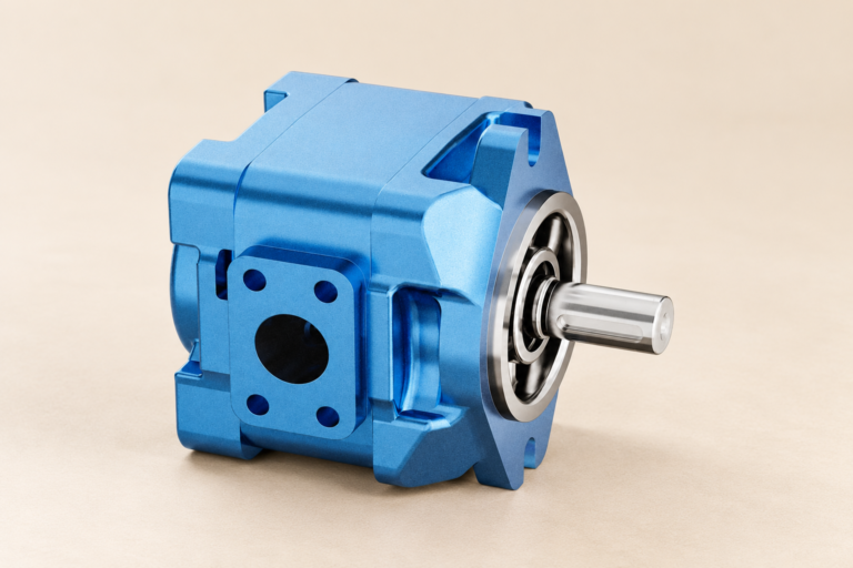
External hydraulic gear pumps are valued for compact construction, relatively few parts, fixed displacement, and straightforward integration. Their delivery contains a periodic component related to tooth engagement, and pressure creates bearing and housing loads that the design must support. Real performance depends heavily on end clearance, bearing condition, housing wear, oil viscosity, speed, and pressure differential.
How an internal gear pump moves oil
The smaller drive gear rotates eccentrically inside the internal ring gear. As the teeth separate, cavities expand and receive fluid. Oil travels around the crescent separator in spaces associated with the two gears. As the teeth re-engage, chamber volume contracts and fluid leaves through the outlet. The crescent separates the suction and discharge paths in designs that use this arrangement.
The longer, smoother meshing sequence can support low-pulsation and relatively quiet operation in suitable designs. Internal gear mechanisms are also used in process pumps for viscous liquids, but that does not mean every industrial internal gear pump is appropriate for mobile hydraulic pressure. Confirm that the exact product is a hydraulic pump with suitable bearings, materials, seals, ports, and ratings.
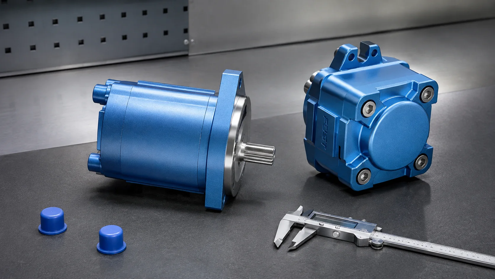
Practical comparison for hydraulic buyers
| Decision factor | External gear pump | Internal gear pump | Verify before ordering |
|---|---|---|---|
| Basic geometry | Two externally toothed gears | External gear inside internal ring gear | Section drawing and product family |
| Package | Often compact and simple | May use a broader ring-gear housing | Envelope, shaft, flange, ports |
| Flow character | Tooth-meshing ripple is an important design factor | Meshing can be smoother in appropriate designs | Noise and ripple data at duty point |
| Displacement | Normally fixed | Normally fixed in common hydraulic versions | Actual displacement and speed range |
| Fluid range | Depends on clearance, seals, and design | Some designs suit higher viscosity | Manufacturer viscosity-temperature chart |
| Service decision | Wear often affects gear, bush, side plate, and housing together | Wear involves gear set, crescent, bearings, and housing | Approved repair limits and matched parts |
Pressure capability cannot be inferred from gear type
Search results often claim that one gear arrangement always produces higher pressure. That shortcut is unsafe. Pressure capability is a property of the complete pump: gear tooth form, shaft and bearing loads, housing stiffness, side compensation, materials, fasteners, seals, lubrication, speed, fluid, duty cycle, and test standard all matter. Compare continuous, intermittent, and peak ratings from the specific manufacturer, including the allowed duration and repetition of peaks.
A positive-displacement pump keeps transferring volume while driven. A blocked outlet can therefore make pressure rise rapidly until a relief path, pump control, drive limit, or mechanical failure intervenes. The University of Florida warns that excessive discharge pressure can cause pump or line damage in its neutral discussion of positive-displacement pump behavior. The relief system must protect the lowest-rated component.
Noise and flow ripple: compare the installed system
Gear meshing creates discrete chamber events. Those events interact with pressure, speed, port timing, housing stiffness, mounting structure, hose length, valve impedance, and entrained air. An internal gear pump may be selected for quieter operation, but a catalog label alone cannot predict machine noise. Ask for sound and ripple data measured under conditions close to the intended operating point.
Installation also changes the result. Rigid panels can radiate structure-borne vibration. A restricted inlet can create cavitation noise that is mistaken for gear-mesh noise. Incorrect shaft alignment can add bearing and coupling noise. Measure sound together with inlet condition, speed, pressure, temperature, and flow before attributing the symptom to the gear layout.
Efficiency and heat generation
Volumetric efficiency describes how much theoretical displacement becomes delivered flow. Mechanical efficiency reflects friction and torque loss. Overall efficiency combines the two. Internal leakage tends to increase with pressure differential and clearance and decrease with higher viscosity, while friction can rise when oil becomes too viscous. There is therefore no single efficiency number that represents every temperature and duty point.
Request performance maps or data at expected speed, pressure, viscosity, and temperature. A pump that appears efficient at one rated point may perform differently during cold start, prolonged standby, low-speed operation, or high-temperature duty. The Texas A&M Turbomachinery Laboratory comparison of positive-displacement and centrifugal pump applications reinforces that pump behavior must be understood from the operating principle and application rather than name alone.
Fluid viscosity and inlet conditions
Both gear types need enough absolute inlet pressure to fill expanding chambers without cavitation. Higher viscosity increases inlet loss; lower viscosity can increase leakage and reduce film strength. Cold start, elevation, reservoir pressurization, line diameter, bends, strainers, filters, and pump speed all affect inlet margin. Use the manufacturer’s viscosity and inlet limits, not a generic preferred oil grade.
Internal gear process pumps may be promoted for very viscous liquids, while a hydraulic internal gear pump is typically designed around hydraulic oil and a defined operating envelope. Do not transfer chemical-process compatibility claims to a hydraulic product. Confirm elastomer, metal, coating, lubrication, and fire-resistant-fluid compatibility in writing.
Contamination, wear, and field evidence
Hard particles can score gear faces, side plates, bushings, crescent surfaces, and housings. Once clearances grow, internal leakage increases, especially at operating pressure and temperature. A pump may still make pressure in a near-blocked test while failing to deliver required flow under load. Record flow across several controlled pressures rather than judging from an unloaded bucket test.
Keep filter debris, oil samples, case or drain evidence where applicable, photographs, and dimensional inspection together. Determine whether wear is uniform, abrasive, adhesive, corrosive, or associated with inlet damage. Replacing gears alone in a worn housing may not restore designed clearance. Follow approved repair limits and cleanliness procedures.
Where each layout commonly fits
External gear pumps commonly serve mobile equipment, agricultural machinery, auxiliary circuits, steering or lubrication duties, and other fixed-displacement systems where compactness and robust simplicity matter. Internal gear hydraulic pumps can fit industrial machinery, presses, machine tools, and systems where low noise and smooth delivery are priorities. These are tendencies, not selection rules.
Direction and port identification also require care during replacement. A housing may be available in several rotations or port arrangements, and reversing shaft rotation without an approved conversion can put suction and pressure on the wrong features. Record the viewing direction, shaft rotation arrow, current port labels, and machine plumbing before removal. Never infer rotation only from an old photograph.
Prance Hydraulic provides an overview of the gear pump product family and its place among hydraulic pump technologies. Related articles explain hydraulic gear pump types, gear pump leakage checks, and pump efficiency evidence.
RFQ checklist
- Required pump principle and reason for the preference
- Displacement, flow, and drive speed range
- Continuous, intermittent, and peak pressure with durations
- Rotation viewed from the defined shaft end
- Shaft, flange, pilot, ports, and installation envelope
- Fluid type, viscosity-temperature range, and cleanliness target
- Minimum inlet pressure and cold-start condition
- Duty cycle, noise target, allowable ripple, and ambient conditions
- Relief arrangement, drive power, coupling, and alignment method
- Existing model code, photos, drawings, and replacement constraints
Educational video: internal gear pumping action

Watch the internal gear pump animation on YouTube. The animation supports concept learning; it does not establish ratings for a particular product.
FAQ
Which is quieter, an internal or external gear pump?
Internal gear designs are often selected for smoother, quieter delivery, but installed noise depends on the exact pump, duty point, inlet condition, mounting, and circuit. Compare measured data.
Can an internal gear pump replace an external gear pump directly?
Not from displacement alone. Confirm shaft, flange, ports, rotation, speed, pressure, viscosity, controls, envelope, and drive requirements.
Are both types fixed displacement?
Most common hydraulic external and internal gear pumps are fixed displacement, but always verify the exact product architecture.
Which gear pump handles higher pressure?
The complete design determines pressure rating. Do not infer it solely from internal or external gear geometry.
What causes a gear pump to lose flow under pressure?
Excessive internal clearance, wear, unsuitable viscosity, high temperature, inlet problems, low speed, or a bypass path can reduce delivered flow as load rises.