Wenzhou Prance Hydraulic Equipment Co., Ltd

Hydraulic Gear Pump Types: How to Separate Geometry From Configuration
The two core hydraulic gear pump types are external and internal arrangements. That distinction tells you how the gears are laid out; it does not settle rotation direction, mounting, porting, fluid conditions, or whether a particular product suits a circuit. The sections below explain the geometry, separate it from configuration labels, and show the information worth gathering before a product discussion.
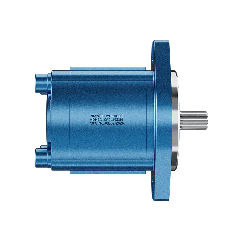
What “hydraulic gear pump types” means in practice
Hydraulic gear pumps are one branch of the wider hydraulic-pump family, alongside designs such as vane and piston pumps. Within the gear-pump branch, the useful first classification is the gear arrangement: external or internal.
That small distinction matters because enquiries often arrive with only the words “gear pump.” A distributor may need to determine whether the buyer is looking at an external layout with two side-by-side gears or an internal layout with one gear operating inside a larger ring-shaped gear. Starting with geometry keeps the conversation clear before product connections and duty details enter the picture.
The term positive displacement describes the working principle behind this family. Rotating elements carry separate pockets of fluid from the inlet side to the outlet side.
In plain language, the pump moves oil in repeated pockets as the gears turn. For a broader view of adjacent families, see the Hydraulic Pumps product category.
The short answer: external and internal gear arrangements
External and internal are the two core arrangements used to describe a hydraulic gear pump. Other labels can still be important, yet they usually identify a configuration, installation choice, or package format rather than a third basic geometry.
The table is a quick way to sort the vocabulary. It is intended to help a reader frame a useful first question, rather than to rank either arrangement as the universal choice.
| Arrangement | Basic geometry | Plain-language picture | First question it answers |
|---|---|---|---|
| External gear arrangement | Two interlocking gears run on separate shafts. | Two matching gears work alongside each other and carry fluid around the casing. | Is the pump described as an external gear layout? |
| Internal gear arrangement | A smaller gear operates inside a larger internally toothed gear. | A smaller gear works inside a larger ring-shaped gear. | Is the pump described as an internal gear layout? |
An external gear pump and an internal gear pump can therefore be compared at the geometry level first. The next decision is to read the product information for the interface and operating details that apply to the intended machine.
How an external gear pump moves fluid
An external gear pump uses two identical interlocking gears on separate shafts. As the gears rotate, fluid fills the spaces around the teeth, travels around the casing, and is carried from the inlet toward the outlet.
That motion is the core hydraulic gear pump working principle. The meshing zone separates the inlet and outlet sides while the rotating tooth spaces transport discrete volumes of fluid. The explanation is useful when matching a drawing, product description, or maintenance conversation to an external arrangement; it is not a performance prediction for a particular machine.

Picture an OEM reader reviewing a component drawing. Seeing two interlocking gears on separate shafts gives that reader a sound basis for calling the layout external. The next questions concern how the unit connects to the machine: ports, mounting, drive coupling, fluid, and the operating conditions that the application supplies.
How an internal gear pump differs in geometry
An internal gear pump differs because the smaller gear operates within a larger internally toothed gear. It is a distinct arrangement, so the name identifies the geometry before it says anything about a final system choice.
The contrast is easiest to hold in mind as a layout question. External designs place the matching gears beside one another. Internal designs place one gear within the other.
Neither name alone states the required flow, the working pressure, the mounting pattern, or the duty of the machine. Geometry is the opening move in selection, followed by the details of the intended installation and use.
For readers comparing a product route, the relevant product information should stay close to the arrangement. Prance lists an Internal Gear Pump HG route for plastic-injection-molding and related servo hydraulic circuits. Its published enquiry fields cover the machine and circuit information needed for that stated context.
Which labels are types and which are configurations?
External and internal identify the basic gear arrangement. Rotation direction and a reversible designation describe other product requirements that must be read with the product documentation.
A reversible description, for example, concerns permitted drive direction. It does not replace the question of whether the pump uses an external or internal gear arrangement.
This separation prevents a common purchasing mistake. A reader may see a familiar word in a catalogue and assume it defines the whole pump. A more useful approach is to record the geometry first, then record the direction, port orientation, mounting, coupling, and other interfaces as separate requirements.
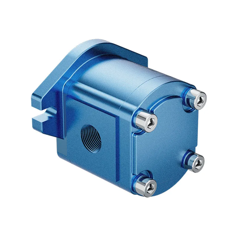
The same approach helps with nameplate or drawing review. A visual check may suggest a layout, while the product sheet supplies the details needed to mount and drive the unit. Keeping those layers separate makes it easier to compare like with like when several product descriptions use different labels.
Build the selection picture before choosing a product route
Geometry starts the discussion, while flow, working pressure, interfaces, fluid conditions, control context, and duty complete the selection picture. Collecting these facts early gives a product conversation a useful technical foundation without asking a type label to do work it cannot do.
For an external route, the key installation questions include ports, mounting, drive coupling, fluid, temperature, and filtration, alongside target flow and working pressure. An internal route may also call for machine type, duty cycle and control interface. These are decision inputs to gather before a product discussion moves forward.
| Information to gather | Why it belongs in the conversation | Example of what to clarify |
|---|---|---|
| Required flow and working pressure | Connects the pump discussion to the circuit demand. | What flow and pressure does the machine require in its operating use? |
| Ports, mounting, and coupling | Defines the installation interface. | Which port connections, mounting arrangement, and drive coupling are present? |
| Fluid, temperature, and filtration | Describes the operating fluid environment. | Which fluid is used, and what temperature and filtration conditions apply? |
| Machine, control interface, and duty cycle | Adds the application context requested for an internal route. | What machine is involved, how is it controlled, and how is it expected to run? |
Gathering this information also improves communication across a supply chain. A distributor can pass a clearer record to an OEM or system integrator, and an integrator can identify which unknowns still belong to the machine owner. That is more productive than treating an arrangement name as a complete specification.
What pump type cannot tell you about a hydraulic circuit
A type label cannot explain heat, falling flow, or a safe control change without the rest of the circuit evidence. It identifies the gear layout, whereas circuit behavior depends on the components, settings, fluid state, measurement method, and operating conditions around the pump.
From the field: In a TractorByNet discussion of gear-pump flow control, a user raised a restriction-and-heat concern. That concern shows why a gear-pump classification identifies layout but cannot diagnose a restriction, measurement issue, or wear condition.
For procurement and maintenance, the distinction remains practical. An operator may report a hot system or an apparent loss of flow while a buyer is still trying to identify the installed pump.
A circuit-level investigation addresses the symptom, while geometry and product identification answer the classification question.
For a symptom-focused discussion, see Hydraulic Gear Pump Leakage. The classification remains useful because it gives the shared vocabulary for external and internal layouts before a specific circuit issue is examined.

External and internal product context for the next conversation
Prance provides an External Gear Pump HDH route for readers who have identified an external arrangement and are ready to assemble circuit and installation inputs. The HDH enquiry fields cover target flow, working pressure, ports, mounting, drive coupling, fluid, temperature, and filtration.
For an internal arrangement in the stated plastic-injection-molding or related servo-circuit setting, the Internal Gear Pump HG route provides a separate product context. Its enquiry fields add machine type, control interface, and duty cycle to the core flow, pressure, fluid, mounting, and coupling discussion. These routes are most useful after the geometry and application facts have been recorded together.
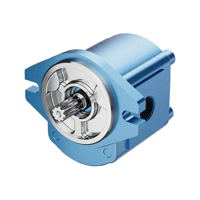
The practical outcome is simple: use external or internal to identify the layout, then bring the system details to the relevant product page. That sequence gives a clearer starting point for an OEM, distributor, or system-integrator conversation than a broad request for a “gear pump” alone.
FAQs
What are the main types of hydraulic gear pumps?
The two core hydraulic gear pump types are external and internal arrangements. External uses two interlocking gears on separate shafts, while internal places a smaller gear within a larger internally toothed gear. Rotation direction should be handled as a separate product requirement.
How does an external gear pump work?
An external gear pump uses two meshing gears to carry fluid in the spaces around the teeth from the inlet side around the casing to the outlet. This is a positive-displacement action: repeated pockets of fluid are moved as the gears rotate.
How does an internal gear pump differ from an external gear pump?
The difference begins with geometry. An internal gear pump has a smaller gear operating within a larger internally toothed gear, while an external gear pump uses two matching gears side by side. The route to consider next depends on the machine and installation information available.
Are gear pumps fixed-displacement pumps?
Gear pumps are commonly described as positive-displacement pumps because the rotating gear spaces carry discrete fluid volumes from inlet to outlet. The term explains the pumping action; product-specific operating details still come from the relevant model information and circuit requirements.
Is a reversible gear pump a separate core pump type?
No. Reversibility refers to an allowed drive direction, so it is a configuration matter rather than an additional core geometry. Confirm the permitted direction in the product information along with the ports, mounting, coupling, and the rest of the installation details.
What information should I prepare before asking for a hydraulic gear pump quotation?
Prepare the required flow, working pressure, ports, mounting, drive coupling, fluid, temperature, and filtration information. For the stated internal-route context, machine type, control interface, and duty cycle are also useful inputs. A complete record makes the product discussion more specific.
Can pump type alone explain heat or falling flow?
No. External or internal identifies a gear arrangement, not the cause of circuit heat or an apparent change in flow. Those symptoms require circuit-level information, including the operating conditions and how the system behavior was observed.