شركة ونزهو برانس للمعدات الهيدروليكية المحدودة

دوائر شحن مخزن هيدروليكي: التشغيل التلقائي، الإيقاف التلقائي، وتفريغ المضخة
A hydraulic accumulator charging circuit replenishes oil until a defined upper pressure is reached, then unloads or destrokes the pump while a check valve retains pressure in the accumulator branch. Charging resumes when branch pressure falls to a lower threshold. The important distinction is between controlling that operating pressure band and setting the accumulator’s gas precharge. They are different tasks, measured under different conditions. A useful design review follows the oil through charging, standby, demand and shutdown, and checks which pressure each control actually senses.
For a machine builder, the practical question is whether the stored oil can satisfy the intended demand while the pump changes state. Reaching the upper pressure once does not prove that the circuit has sufficient usable volume, an acceptable recharge time or a safe isolation arrangement.
Follow four operating states
During charging, the pump supplies the accumulator through a nonreturn path. The load may consume flow at the same time. Pump delivery therefore has to cover both demand and the flow needed to restore storage. If demand approaches available delivery, pressure may rise very slowly even when every component is functioning as intended.
At the upper switching point, the charging control changes the supply condition. In a fixed-displacement arrangement, an unloading path can return pump flow at a lower pressure. A compatible variable pump may instead reduce delivery under an appropriate control arrangement. These are different circuit designs; a generic pressure compensator is not automatically an accumulator unloading control.
During demand, the accumulator releases oil and its pressure falls. The check valve separates this stored pressure from the unloaded pump branch. At the lower switching point, the supply re-enters its charging state. The actuator must still receive adequate pressure during the transition. This is why measuring only the upper limit misses an important part of the operating cycle.
Shutdown is a separate state. Stopping the electric motor does not establish that downstream pressure is zero. Identify every isolated volume and the designed discharge method. The energy isolation procedure must account for stored hydraulic energy before anyone disconnects a hose, removes a valve or services an actuator.
Separate three pressure decisions
Gas precharge establishes the gas-side starting condition under the accumulator manufacturer’s specified procedure. The operating cut-in point determines when oil replenishment resumes. The cut-out point determines when replenishment stops or the pump unloads. None of these values should be selected by copying a percentage from a different accumulator or charging valve.
Begin with the load’s minimum pressure requirement at the point of use. Add the pressure losses between storage and the actuator under the required flow condition. Then consider the permitted operating range of the accumulator, pump, valves and connected equipment. The pressure band must leave room for switching behavior and transients, rather than merely sitting below a nominal nameplate maximum.
Also distinguish the charging controller from the protective relief function. The charging controller establishes normal cycling. The approved overpressure protection must still address credible faults. A commissioning record should show how each function was verified and which component limits apply. Successful unloading in normal operation is not evidence that a separate protection function has been tested.
Use the right pressure measurement points
Place the accumulator-side measurement downstream of the isolating check valve. A pump-outlet gauge upstream of that valve can show low pressure during standby while the accumulator remains charged. Those readings are consistent with successful unloading, not necessarily evidence of a failed gauge.
For diagnosis, compare pump-side pressure, accumulator-side pressure and the charging command or valve state on a common time base. Mark the beginning of demand and the beginning of recharge. Record oil temperature and machine operating mode, because a comparison made with a different demand cycle may be misleading.
A sensor should be selected for the expected pressure, transient exposure, response and mounting conditions. Use existing approved test points or an engineered test arrangement. Do not open a charged circuit to improvise a connection. If an electronic controller uses a remote pressure signal, confirm that the logged channel corresponds to the same location used by the controller.
Build a cycle calculation before changing settings
A first estimate of replenishment time is the usable oil volume to restore divided by the net charging flow. Express both on compatible units. This is a volume-balance estimate, not a prediction of the complete transient response. It ignores changes in pump delivery, simultaneous demand, leakage and the switching delay unless those are included in the inputs.
For an explicitly hypothetical example, suppose a cycle removes 1.2 litres and the measured net charging flow averages 12 litres per minute. The ideal replenishment time is 1.2 / 12 = 0.1 minute, or six seconds. If the next demand arrives sooner, simply increasing the upper pressure does not resolve the flow deficit. These numbers are teaching assumptions, not Prance product data.
Usable oil volume is not the accumulator shell’s nominal volume. It depends on gas behavior, pressure limits, temperature, precharge and the accumulator design. Use the manufacturer’s sizing method for the actual duty. A calculation based on an assumed constant gas temperature may be unsuitable for a rapid repeated cycle without further verification.
A separate power check can compare pump pressure and flow during standby. Hydraulic power in kilowatts is pressure in bar multiplied by flow in litres per minute, divided by 600. Input power also includes losses. Use measured conditions, and do not claim an energy saving from the unloading label alone. The duration of each state matters as much as its instantaneous pressure.
Read cycling symptoms as a sequence
Rapid cycling can reflect high continuous demand, leakage, inadequate usable storage, a narrow switching band or an incorrect sensing arrangement. It can also be a response to an application whose demand has changed. Start with the recorded cycle rather than assuming the charging valve is defective.
If accumulator pressure falls while the machine is idle, identify all normal consumers before conducting a leakage test. Pilot flow and intentional bleed paths can consume stored oil. An approved isolation test may help separate branches, but the test must preserve protection and controlled discharge. Closing an arbitrary valve can create a trapped, unprotected volume.
If the pump never unloads, compare available delivery with load demand and inspect the switching signal. If the accumulator reaches the upper threshold but the pump remains at high power, determine whether the circuit has actually changed state. A closed outlet with a pump held at high pressure is different from low-pressure unloading.
| ملاحظة | مقارنة مفيدة | Next engineering question |
|---|---|---|
| Frequent short recharge cycles | Idle and operating pressure traces | Is oil being consumed, leaking, or stored over too narrow a usable band? |
| Slow pressure recovery | Net charging flow and simultaneous load flow | Is sufficient pump delivery available throughout recharge? |
| Pump pressure falls but storage pressure remains | Measurements on both sides of the check valve | Is the nonreturn separation operating as intended? |
| Pressure falls immediately after shutdown | Designed discharge state and active consumers | Is this intended depressurization or an unintended loss path? |
| High standby heat | Pump pressure, return flow and state duration | Has the pump actually entered its intended low-demand condition? |
This is a diagnostic planning table, not a set of universal settings. The university circuit references listed below explain the charging and unloading functions; the test decisions here must be adapted to the installed machine.
Match the pump and charging control
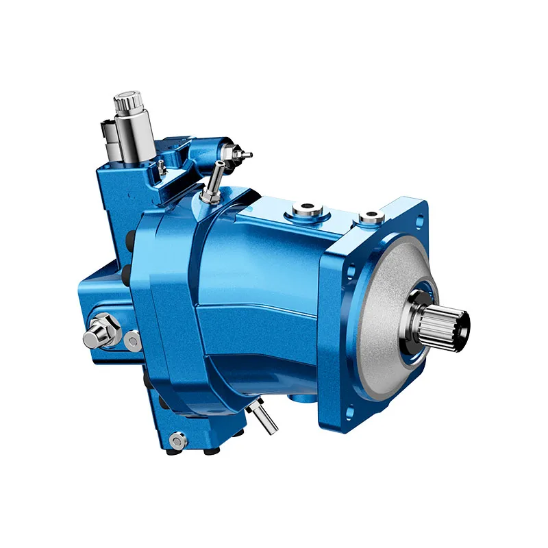
When reviewing a replacement pump, confirm the complete control configuration, displacement, drive speed, rotation, inlet conditions and approved fluid. A photograph of an axial piston pump does not show how it will interact with a remote charging valve. The control symbol and ordering code are essential.
For a variable-displacement pump, establish which signal moves the control between charging and standby, where that signal is sensed and what happens if it is lost. Check the interaction with the pump’s pressure cutoff and any load-sensing functions. Independently correct controls can still interact poorly if their operating ranges overlap without a clear hierarchy.
For a fixed-displacement pump, review the unloading path’s capacity and the pressure loss at the actual flow. Confirm the check valve’s direction and its documented leakage performance. Neither the charging valve nor the check valve should be selected by thread size alone. The mounting, pressure rating, flow characteristic and response requirements all belong in the selection.

Commission one complete demand cycle
Write acceptance criteria before running the machine. They should include minimum pressure at the load, upper charging pressure, recharge duration, acceptable switching behavior, standby power and the shutdown state. Use the equipment manufacturer’s limits; this guide does not supply replacement settings.
Run the approved sequence from a known initial condition, then repeat it under the relevant temperature and demand conditions. Record whether the lower threshold occurs before, during or after the actuator demand. A short bench demonstration may not reproduce the accumulated heat or repeated demand of production service.
If a change is needed, document one controlled change at a time. Preserve the original setting, the responsible approval and the before-and-after trace. Recheck protective functions and discharge behavior after the final configuration is accepted. A quieter cycle alone is not a sufficient acceptance result.
Prepare a useful configuration inquiry
Send the circuit drawing revision, pump code, accumulator identification, approved gas precharge procedure, operating pressure band and demand history. Include measured charging flow, temperature and the timing of repeated cycles. Clearly mark whether the request concerns a new design, a replacement or an existing cycling problem.
For the pump supplier, distinguish required documented capabilities from assumptions still under review. Ask for confirmation of the proposed control arrangement and its operating limits. Do not interpret the presence of an A10VO-family product photograph as approval for a particular accumulator charging architecture.
A good inquiry describes what the actuator must receive and when. It also describes the permitted standby condition and safe shutdown behavior. Those details make it possible to evaluate a pump and control combination without guessing from the maximum working pressure alone.

الأسئلة الشائعة
هل شحن الزيت هو نفسه شحن الغاز المسبق؟
لا. دائرة الشحن تعيد تعبئة زيت هيدروليكي أثناء التشغيل. الشحن المسبق للغاز هو حالة خدمة منفصلة للمكبس يتم تحديدها باستخدام إجراء الشركة المصنعة والمعدات المعتمدة. لا تستنتج أبدًا الشحن المسبق من مقياس ضغط التشغيل العادي.
لماذا ينخفض ضغط المضخة بينما يظل ضغط المخزن عاليًا؟
في ترتيب التفريغ، يمكن للمضخة العودة إلى حالة ضغط أقل بينما يعزل صمام التحقق الزيت المخزن. قارن القياسات على جانبي صمام التحقق وتحقق من حالة الدائرة المقصودة.
هل تحتاج المضخة المعايرة للضغط دائمًا إلى صمام تفريغ؟
No universal arrangement applies. The pump control, required standby condition, accumulator isolation and machine demand determine the design. Confirm the complete circuit and control code instead of adding a valve by analogy.
هل يمكن لنطاق ضغط أكبر أن يعالج التكرار السريع؟
قد يغير الدورة، لكنه يغير أيضًا الضغط المتاح والحجم المخزن. حدد أولاً الطلب، والتسرب، والسعة القابلة للاستخدام، ثم تحقق من أي نطاق مقترح مقابل متطلبات المكبس الهوائي، والمكونات، والمشغل.
What proves that the charging circuit works?
يجب أن يُظهر دورة كاملة معتمدة الضغط المطلوب على الحمولة، توقيت إعادة الشحن، نقطة التبديل العلوية، حالة الاستعداد، والإيقاف المُتحكم فيه. قم بتسجيل هذه الحالات عبر نطاق درجة الحرارة والطلب ذات الصلة بدلاً من الاعتماد على قراءة ضغط واحدة.
Related product and engineering resources
مضخة إزاحة متغيرة الأصلية A10VO سلسلة 31, hydraulic pump product range, كيفية إعداد سجل اختيار المركم الهيدروليكي للمراجعة, خطوط إشارة استشعار الحمل: الفتحات، التسرب، والاستجابة البطيئة. Confirm the complete product code and application requirements when requesting a configuration review.
Technical references
- Wolfram accumulator charging circuit
- VSB hydraulic mechanisms
- NIOSH: preventing injuries from uncontrolled hazardous energy
University lesson: hydraulic accumulators
8.2 – Subsystems: Hydraulic accumulators, Classifications, Applications, Accumulator physics by NPTEL IIT Kharagpur provides background on accumulator applications, compressed-gas behavior and stored energy. It supplements the component fundamentals; it is not a test procedure for the complete circuit discussed above.