شركة ونزهو برانس للمعدات الهيدروليكية المحدودة

التحكم في تغيّر حجم المحرك: الضغط، الهيدروليكي، والكهرهيدروليكي
Hydraulic motor displacement control types differ in the command they accept and the operating condition they are designed to manage. Hydraulic pilot control, electric proportional control, two-position switching, and pressure-related automatic control can all change a variable motor’s displacement, but they do not produce interchangeable machine behavior. Choose the control around the required torque–speed envelope, command system, and response to a lost signal. A motor family name or connector photograph cannot confirm those details. This guide compares control functions without assigning another manufacturer’s control codes, calibration, or optional features to a Prance product.
Start with what displacement changes
Motor displacement is the geometric volume associated with one shaft revolution. At an unchanged supplied flow, reducing displacement generally increases the potential speed. At an unchanged pressure difference, reducing displacement generally reduces available torque. Actual results also depend on volumetric and mechanical losses, circuit restrictions, and the load.
The control therefore changes the relationship between hydraulic input and shaft output. It does not provide unlimited speed at the same torque. A machine that shifts to a smaller displacement for travel must still have enough pressure capability to carry the resulting load. The motor’s approved speed, pressure, minimum displacement, and operating mode remain binding.
Displacement control is also different from throttling the supply flow. A valve can slow a fixed-displacement motor by reducing the flow reaching it; a variable motor can change speed by changing its geometry. Both approaches may exist in one system. Identify which device commands each part of the operating range before proposing a replacement.
Hydraulic pilot proportional control
A hydraulic proportional control uses a pilot-pressure command to request an intermediate displacement within the permitted range. Its attraction is direct compatibility with an existing hydraulic control system. The displacement response can depend on pilot-pressure range, command direction, available control supply, and the selected controller arrangement.
Do not infer that more pilot pressure always means more displacement. The relationship must be stated for the complete motor and control code. Two units with the same pilot port can have different command characteristics or end positions. The hydraulic circuit must also provide the required command pressure and release behavior during startup, stopping, and a loss of supply.
For integration, compare the commanded range with the pressure actually available at the motor control port under load. A pilot regulator’s setting measured elsewhere may not establish the same pressure during a transition. Losses, restrictions, or another function sharing that supply can change the command reaching the motor.
Electric proportional control
An electric proportional arrangement converts an electrical command into a displacement request through its electrohydraulic mechanism. This can support coordinated machine control, ramps, and programmable operating modes. The motor still needs the hydraulic conditions specified for the control to move and remain within its approved envelope.
Confirm whether the interface expects current, voltage, or another defined input, and identify whether the driver is external or integrated. Coil voltage alone does not describe the command law. The pinout, allowable signal range, driver characteristics, protection, connector sealing, and behavior with an open circuit must all match the machine design.
Electronic command does not automatically mean closed-loop speed control. A commanded displacement can change while actual speed still varies with supply flow, leakage, and load. If precise speed is required, establish the feedback sensor, control algorithm, and limits in the complete system. Do not advertise speed accuracy from the presence of an electrical connector.
Two-position displacement switching
A two-position control changes between defined displacement endpoints rather than continuously selecting every intermediate value as an operator command. The actuation can be hydraulic or electrical. This is useful where the machine needs distinct operating ranges, but the transition still affects torque, speed, and circuit pressure.
Compare the two endpoint displacements and the conditions allowed during shifting. A motor can require a minimum supply pressure or a specified load condition for the shift. The rate of change may be controlled by the design or external circuitry. Avoid assuming an abrupt electrical command creates an equally abrupt, safe mechanical transition.
For a drive with inertia or an overrunning load, shifting must be considered alongside the braking and charge arrangements. A speed increase after reducing displacement may exceed the intended machine behavior even if the motor remains below one catalog speed value. The complete duty, load direction, and pressure relationships matter.
Pressure-related automatic control
A pressure-related control adjusts displacement in response to a defined working-pressure condition. In a suitable arrangement, increasing load pressure can request more displacement to support torque, with a corresponding change in potential speed at a given flow. The exact relationship, sensing arrangement, start point, and control range are specific to the selected unit.
This differs from an operator directly commanding a displacement through a pilot regulator. The operator may request machine motion while the motor controller responds to load pressure. A replacement that changes this relationship can make the drive accelerate, decelerate, or shift differently from the original design.
Ask how the controller behaves during pressure reversal, braking, startup, and a sudden reduction in load. A short description such as automatic control is insufficient. If the manufacturer provides selectable overrides or defeat functions, confirm their documented purpose and availability for the actual configuration; do not assume the option exists across the entire family.
Compare the interfaces and the decisions they leave open
This qualitative comparison describes control categories. It is not a compatibility matrix for specific model codes.
| Control category | Primary request | Useful integration question | Common assumption to avoid |
|---|---|---|---|
| Hydraulic proportional | Pilot pressure | What pressure range and direction request each displacement? | More pilot pressure always means more displacement |
| تناسبي كهربائي | Defined electrical command | What driver, input range, and failure behavior are required? | A voltage label proves the command interface |
| Hydraulic two-position | Hydraulic switching condition | Which endpoints and shift conditions are approved? | Every load condition permits an unrestricted shift |
| Electric two-position | Electrical switching command | What happens after signal loss or a broken connection? | Unpowered always means the safest machine state |
| Pressure-related automatic | Working-pressure condition | How does displacement respond across the load cycle? | A pressure response provides closed-loop speed control |
The right choice depends on the whole control system. Adding electronics can provide command flexibility but also requires a compatible driver and a defined fault response. A hydraulic interface can suit an existing machine but still require careful verification of pilot supply and routing. Neither category is inherently the right answer for every application.
Calculate the torque–speed consequence before choosing endpoints
For an ideal motor, speed in rpm is approximately 1,000 × flow in L/min divided by displacement in cm³/rev. Ideal torque in N·m is approximately pressure difference in bar multiplied by displacement in cm³/rev divided by 20π. These are dimensional engineering relationships, not guaranteed performance values.
Consider an explicitly hypothetical input of 60 L/min and 150 bar pressure difference. At 100 cm³/rev, ideal speed is 600 rpm and ideal torque is about 239 N·m. At 50 cm³/rev, ideal speed doubles to 1,200 rpm while ideal torque halves to about 119 N·m. These values ignore losses and do not represent a Prance rating.
The example explains why a smaller displacement cannot preserve the same torque merely because the control command is available. Real selection must use documented efficiency, continuous and intermittent limits, minimum allowed displacement, and maximum speed under the relevant pressure conditions. Compare the load’s required torque at both speeds, including acceleration and braking demands.
Define signal loss as a machine condition
A control’s unpowered or unpressurized position is a component characteristic. Whether that position is safe depends on the machine. Moving toward maximum displacement can increase available torque and reduce speed potential, but it can also change braking pressure or stopping behavior. Moving toward minimum displacement can reduce drive torque while permitting a higher speed for an imposed flow.
Do not equate either endpoint with an independently verified safety function. Establish what the circuit does when electrical supply, pilot supply, main flow, or feedback disappears. These are different failures and may not produce the same result. The mechanical brake, load-holding devices, and emergency stopping arrangement need their own assessment.
Before testing failure behavior, secure the equipment and use the approved procedure. Never unplug a control on a moving machine merely to discover its default position. Unexpected displacement changes can alter speed and load control. Isolate stored energy before changing connectors, pilot lines, or control hardware.
Match a replacement to the actual configuration
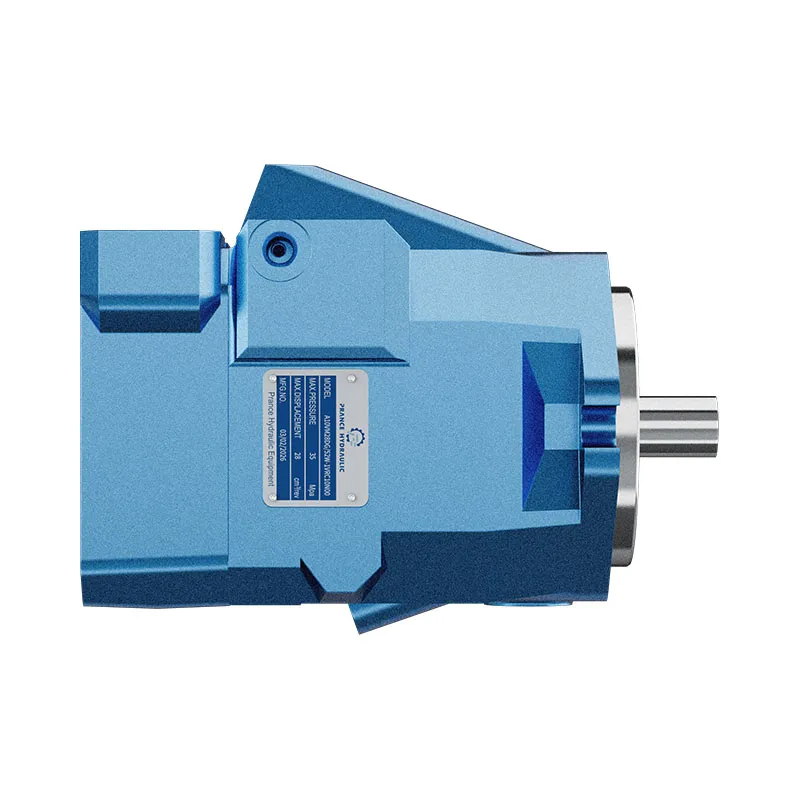
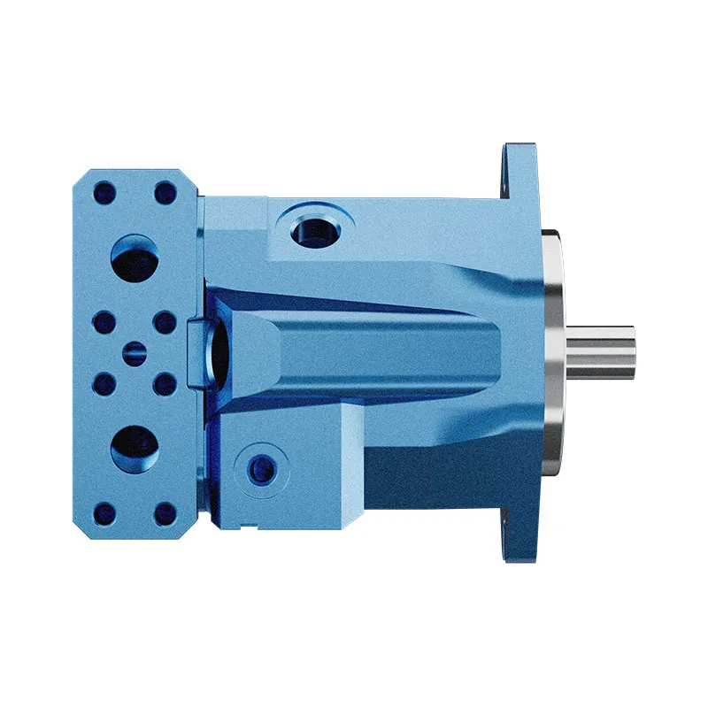
The Prance A10VM variable-displacement piston-motor page is a relevant starting point for a motor inquiry. It does not confirm that all control categories described here are offered on that product. Provide the complete existing model code and documentation, then request confirmation of the required control and operating envelope.
Include the command interface, displacement endpoints, command direction, pilot or electrical supply, shaft and mounting, rotation, ports, case-drain arrangement, and any attached valves or sensors. Explain whether the motor drives a resisting load, can be driven by the load, or operates in both conditions. Exterior fit alone does not prove functional interchangeability.
Acceptance should check displacement response, speed and torque at representative points, startup, shift transitions, and the approved response to lost command. Compare tests at consistent fluid temperature and supply conditions. Keep the agreed command-to-displacement information with the maintenance record so future replacements can be reviewed against evidence rather than memory.
الأسئلة الشائعة
هل يوفر التحكم في الإزاحة الكهربائية تنظيم سرعة تلقائي؟
ليس بالضرورة. يطلب الإزاحة من خلال واجهة كهربائية. يتطلب تنظيم السرعة بدقة وجود نظام تغذية راجعة مناسب وترتيب تحكم في النظام بالإضافة إلى تحكم المحرك.
هل يمكن استبدال التحكم الهيدروليكي والكهربائي على نفس جسم المحرك؟
Do not assume so. Available hardware, internal control supply, calibration, and approved configurations vary. Confirm a documented conversion or order the complete required configuration.
هل التحكم ذو الوضعين هو نفسه عكس الدوران؟
لا. يغير تبديل الإزاحة ذو الوضعين حجم الدوران لكل دورة بين النقاط النهائية المحددة. يعتمد اتجاه الدوران على المحرك وترتيب تدفق الضغط والدائرة.
لماذا يعتبر الحد الأدنى للإزاحة جزءًا من الاستفسار؟
It influences speed, available torque, and the approved operating envelope. A smaller nominal endpoint is not automatically acceptable for the required load and pressure.
أي نوع من التحكم هو الأفضل لاستبدال برانس؟
The suitable type is the one whose documented command, response, failure behavior, and operating limits match the machine. Submit the complete specification rather than selecting from the control category alone.
المنتج والموارد الهندسية ذات الصلة
توفر سلسلة مضخة ذات إزاحة متغيرة OEM A10VO 31 عائلة منتجات ذات صلة لاستعلام التكوين. لا يثبت اسم العائلة والصورة الخارجية للمصدر توفر كل التحكم أو الخيار الذي نوقش هنا. لا تصور هذه الرسوم التوضيحية المفاهيمية مكونات المنتج الداخلية أو تحدد حدود التشغيل. أكد الرمز الكامل والوثائق المعتمدة. الموارد ذات الصلة: محرك مكابس متغير الإزاحة A10VM, نطاق المحرك الهيدروليكي, متى يكون المحرك ذو الإزاحة المتغيرة أو الثابتة مناسباً؟, محركات هيدروليكية بسرعة مزدوجة: تحويل السعة تحت الحمل.
مصادر وحدود هذا الدليل
تدعم مراجع الجامعة والحكومة المبادئ العامة للهندسة والسلامة. يوفر هذا الدليل منطق اختيار مستقل وحسابات افتراضية صريحة. لا تعتبر رموز التحكم، والإعدادات، والتقييمات الخاصة بالمصنع مرجعًا لمواصفات منتج Prance. أكد التكوين الكامل المطلوب.
- NPTEL: أساسيات هيدروليكا الزيت الصناعية والهوائية
- NIOSH: الوقاية من الإصابة الناتجة عن الطاقة الخطرة غير المسيطر عليها
- IIT Madras NPTEL: hydraulic motor performance and worked relationships
- VSB Technical University of Ostrava: hydraulic mechanisms and component controls
درس جامعي: مبادئ التشغيل
NPTEL-NOC IITM presents 6.3 – Hydraulic Motors. The lesson supports the motor displacement, flow and shaft output used in this discussion; it is not a model-specific performance or installation approval.