Wenzhou Prance Hydraulic Equipment Co., Ltd

Hydraulic Cartridge Valve Cavities: Why Matching Threads Is Not Enough
Hydraulic cartridge valve cavity standards describe the receiving interface in the manifold. Matching a thread is only the first check. A replacement must also match the cavity’s bore steps, depths, seal-contact surfaces, port positions and applicable tolerances, then satisfy the required hydraulic function. A cartridge that screws into a block can still connect the wrong passages or leave a seal unsupported.
Use the exact valve code and the controlled cavity drawing as the starting point. Compare drawing revision, interface designation and port function before ordering or installing a substitute. This guide focuses on screw-in cartridge cavities; slip-in logic elements and subplate-mounted directional valves use different interfaces and require different drawings.
Identify the architecture before measuring anything
A screw-in cartridge normally uses its threaded body to locate and retain the functional element inside a machined cavity. The cavity contains more than a threaded hole: smaller diameters and sealing regions position the cartridge relative to the manifold passages. External appearance rarely reveals all of those features.
A slip-in cartridge uses a different installation arrangement, typically involving a sleeve and a retaining or control cover. A subplate-mounted directional valve seals against a mounting face rather than occupying a screw-in cavity. Describing all three as cartridge-compatible obscures the actual interface that must be checked.
SAE’s public abstract for its cartridge-cavity paper distinguishes screw-in and slip-in architectures. That historical paper is useful for terminology, not as a current interchange chart. Establish the real architecture from the equipment and component documents before using any standard number in a purchase specification.
Treat a standard number as a defined scope
ISO 7789 covers cavities for two-, three- and four-port screw-in cartridge valves. ISO/TR 17209 addresses screw-in cavities with UN and UNF threads. Their titles and official scopes do not mean that every commercially available cartridge of similar size conforms to them. Obtain a clear conformity statement and the exact cavity identification for the proposed component.
ISO 5783 concerns identification codes for interfaces defined in other international standards. An identification code points to a defined interface; it is not a blanket certificate of pressure capacity, valve function or performance. Do not interpret a seller’s abbreviated cavity label as a complete standard designation without clarification.
The standards references in this article identify scope and terminology only. They are not machining instructions, reproduced tolerance tables or an assertion that a particular Prance product uses those cavities. For manufacture and acceptance, use the complete applicable standard and the approved component and manifold drawings.
Compare the complete axial profile
Lay the cartridge installation drawing and manifold cavity drawing side by side using the same datum. Compare every specified diameter and depth, the seating location and the clearance needed by the cartridge nose. A thread designation does not establish where the lower sealing surfaces or cross-drilled passages occur.
Two cavities can share a thread yet differ in the distance from the seating face to a lower bore step. If a seal lands partly across a passage or relief, the resulting fault may be internal leakage rather than an obvious external leak. A deeper feature can also interfere with the cartridge nose even while the thread appears to engage normally.
Use the drawing to decide which features require inspection and which gauges or methods are suitable. Hand calipers and a thread gauge can support identification, but they do not verify inaccessible bore geometry, surface finish or all tolerances. Where inspection access is limited, obtain the manufacturer’s accepted verification method.
Check seal support and insertion paths
Identify each seal and backup element on the cartridge drawing. Then locate the corresponding finished bore surface in the cavity. Check the specified surface condition and the transitions the seal must cross during installation. An intact new seal does not compensate for a damaged land or an incompatible cavity profile.
A seal can be cut during insertion or left without the intended support after seating. Either condition can create a fault that appears only under pressure or after a temperature change. Inspect the cavity under the approved clean maintenance procedure and reject damage outside the permitted acceptance criteria.
Seal material is a separate question from cavity geometry. The replacement must suit the actual fluid and operating conditions, and the seal kit must belong to the selected cartridge configuration. Do not substitute a similarly sized O-ring based only on appearance. Use the component supplier’s installation guidance, including the required lubrication and replacement parts.
Map ports by function, not position alone
Number the cartridge ports according to its own document and trace each to the manifold schematic. Establish which passage supplies pressure, carries controlled flow, drains a spring chamber or receives a pilot signal. A physical opening at the same axial level does not prove the same hydraulic role.
For a directional or check function, compare the permitted flow direction and the de-energized or spring-return state. For a pressure-control function, identify the sensed pressure, regulated path and drain conditions. For a flow-control function, confirm the controlled direction and any bypass or reverse-flow path.
A shared dimensional cavity can accommodate valves with different functions. Therefore, mechanical fit and functional interchange must be separate approvals. When the original function is uncertain, do not use a trial installation and machine movement to identify it. Recover the schematic and full code before proceeding.
Use an interface acceptance table
This qualitative table organizes a replacement review. It contains no universal cavity dimensions or product-specific installation limits; the approved drawings provide those values.
| Check | Evidence needed | Reason to reject or pause |
|---|---|---|
| Thread form and engagement | Exact thread designation and installation drawing | Similar diameter but different form, pitch or engagement |
| Bore steps and depths | Dimensioned cavity drawing with revision | Unverified land position or nose clearance |
| Seal-contact surfaces | Specified diameters, finish and inspection results | Damage, unsupported seal or incompatible transition |
| Port routing | Cartridge symbol and manifold schematic | Correct fit but wrong pressure, drain or flow connection |
| Installation and retention | Component-specific procedure and torque | Torque copied from another cavity or material |
| Hydraulic suitability | Pressure, flow, leakage and state requirements | Interface match without functional approval |
Complete the comparison against the same revision set. If the cavity drawing changes during procurement, reopen the affected checks rather than carrying forward an approval based on an obsolete interface.
Distinguish cavity fit from pressure and flow capability
A cavity designation describes an interface. The pressure capacity of the completed assembly also depends on the cartridge, manifold design, material, wall thickness and other construction details. A thread match does not establish the safety of the surrounding block or nearby cross-drillings.
Similarly, a compatible interface does not guarantee the same pressure drop at the required flow. Two valves can occupy the same cavity while having different metering geometry, cracking characteristics, leakage or response. Compare performance under the actual flow direction and operating conditions, not only a headline maximum flow number.
Use the most restrictive applicable limit for the approved assembly. If the manifold documentation is missing, a replacement cartridge’s rating cannot fill that gap. Obtain the block’s design basis or an engineering review before increasing pressure, changing function or accepting a substantially different operating condition.
Keep subplate-mounted products out of cartridge claims
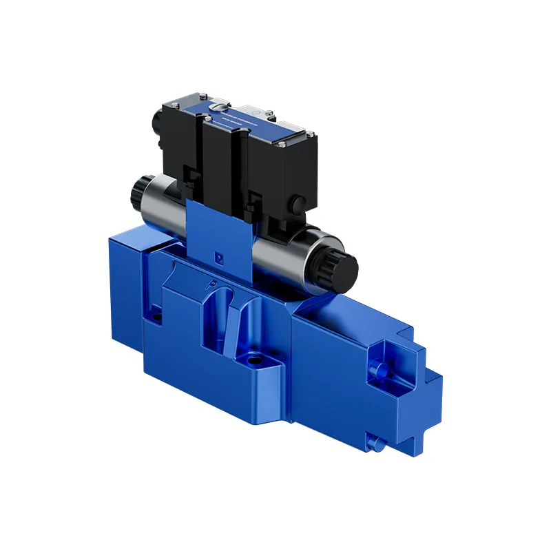
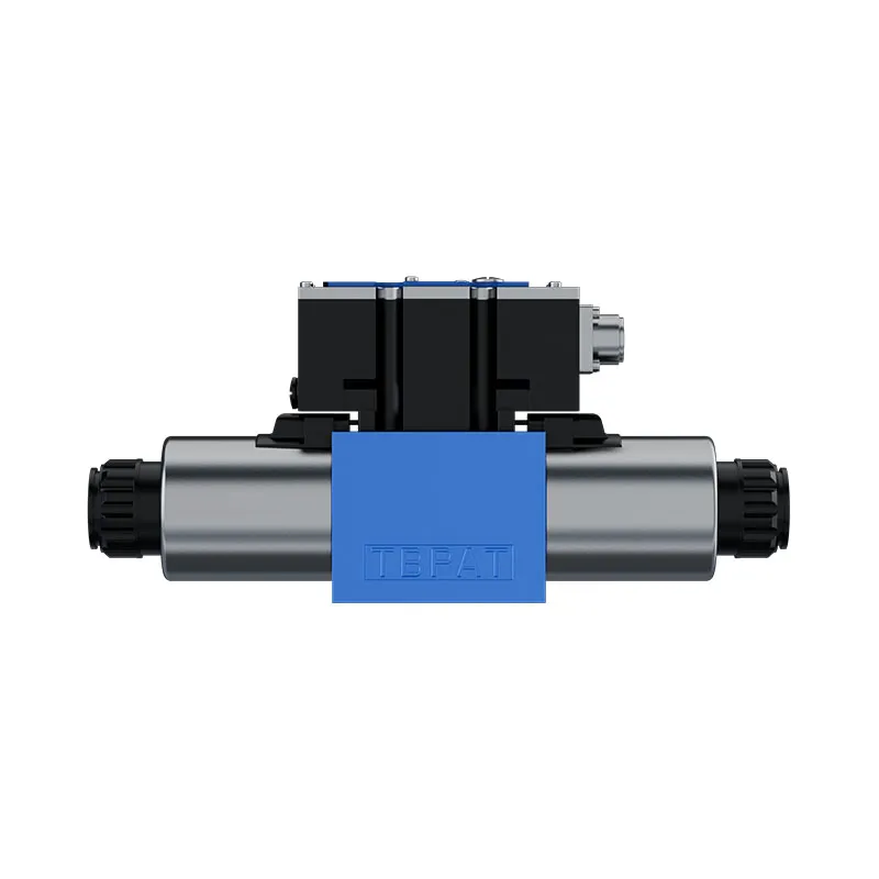
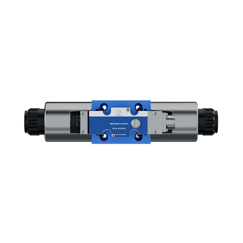
Prance lists proportional directional valves such as the 4WRAE family. Its original product photographs here show a related directional-control architecture for comparison. They are not screw-in cartridge photographs and do not prove a cavity standard, threaded interface or cartridge interchange.
The distinction is useful when a purchasing request contains only a general description such as hydraulic control valve. Before requesting a replacement, identify whether the original mounts on a face, screws into a cavity or uses a slip-in element and cover. That decision determines which drawings and seals must be compared.
For a subplate valve, request the applicable mounting-face drawing and port arrangement. For a cartridge, request the exact cavity drawing. Do not apply an NG-size or mounting-face description to a threaded cavity merely because both components perform directional control.
Inspect and install under the approved procedure
Isolate hazardous energy and support any load before removing the existing component. Pump shutdown alone does not remove accumulator energy or pressure trapped behind a valve. Never loosen a cartridge to determine whether the circuit is pressurized, and do not search for a leak with a hand.
Protect the open cavity and keep debris out of the manifold. Follow the supplier’s cleaning, seal preparation, insertion and tightening instructions for the specific cartridge and block. Installation torque is configuration-specific; a value from another valve with the same nominal thread is not a reliable substitute.
If the cartridge fails to seat as documented, stop. Increasing torque can mask interference, damage the seals or overload the manifold thread. Compare the parts and drawings outside the energized machine rather than forcing a questionable fit into service.
Build the RFQ around a verifiable replacement
Send the complete original code, photographs of accessible identification, the circuit symbol and the cavity drawing with its revision. Include the fluid, temperature range, pressure conditions, required flow direction and expected normal and power-loss states. Mark unknown items instead of filling them with assumptions.
Ask the proposed supplier to return a point-by-point interface and function comparison. Require any deviation to be visible: different seal material, altered leakage, changed drain arrangement or a performance difference can matter even when dimensions agree. A statement that a valve fits a common cavity is not a completed engineering review.
After an authorized replacement, verify external sealing, expected function and controlled actuator behavior under the machine’s commissioning procedure. Check the relevant unloaded and loaded states without exceeding approved limits. Retain the accepted codes, drawings and configuration so the next replacement does not restart from an unidentified threaded body.
Frequently asked questions
Does the same thread prove cartridge interchangeability?
No. It does not establish the internal cavity profile, seal support, port positions or hydraulic function. Compare the complete controlled drawings and the functional requirements before acceptance.
Can one cavity accept valves with different functions?
Yes, a dimensional interface can be used by different functional cartridges. That is why a cavity match must be followed by a separate check of flow paths, normal state, sensing and drain arrangements.
Is a cavity standard also a pressure rating?
No. Interface conformity alone does not establish the pressure capacity of the cartridge and manifold assembly. Check each applicable component and construction limit in the approved design.
Can I machine a cavity from this article?
No. This is a comparison and procurement guide, not a machining specification. Use the complete applicable documents, controlled drawings, approved tooling and required inspection procedure.
Does the pictured 4WRAE use a screw-in cavity?
The photograph illustrates a related subplate-mounted directional-valve family for comparison. It is not evidence of a screw-in cartridge cavity. Obtain the correct interface drawing for the actual product code.
Related product and engineering resources
Proportional Valve 4WRAE, hydraulic valve product range, Hydraulic Valve Interchange Guide: Symbols, Ports, and Performance, Hydraulic Valve Flow Rating: Read Pressure-Drop Curves Correctly. Confirm the complete product code and application requirements when requesting a configuration review.
Technical references
- ISO/TR 17209:2013 official scope: UN and UNF screw-in cavities
- ISO 7789:2007 official scope: screw-in cartridge cavities
- SAE 931192: Cartridge Hydraulic Valve Cavities; public abstract only
Further learning: hydraulic valves
mod-12 lec-12 General Control Valve Analysis by nptelhrd provides background on valve functions. The NPTEL lesson explains directional-valve metering and flow paths; it does not certify a particular cartridge, damping option or interchange. It supplements the component fundamentals; it is not a test procedure for the complete circuit discussed above.