Wenzhou Prance Hydraulic Equipment Co., Ltd

Sizing a Hydraulic Motor to Drive a Water Pump: Head, Flow, and Shaft Power
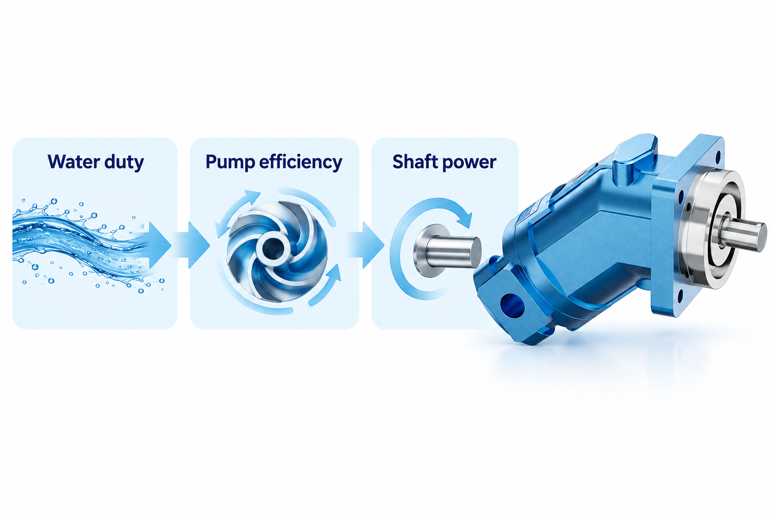
Hydraulic motor driven water pump sizing starts with the water pump’s duty point: required water flow, total dynamic head, operating speed and shaft power. Convert the water duty into shaft demand using the water pump’s efficiency, then choose a hydraulic motor that can deliver that torque and speed with the available oil flow and pressure difference. Check startup, the full operating curve, case-drain conditions and coupling loads before approving a combination. Matching a motor to the water pump’s discharge pressure alone is incorrect because water pressure, oil pressure and shaft torque belong to different parts of the power chain.
Define the water duty before selecting the hydraulic motor
Begin with the required delivery flow and the total dynamic head at that flow. Total dynamic head accounts for the relevant elevation and pressure differences, together with losses in the water circuit. A pipe’s vertical height alone is rarely the complete duty. Hoses, bends, valves, nozzles and other equipment can change the head required to deliver the specified flow.
Write down the operating range as well as the normal point. A transfer pump feeding two different destinations may operate against different system curves. A dewatering pump sees changing water levels. An irrigation system may have multiple zones. These conditions can change shaft demand and move the pump away from the intended operating region.
Identify the water pump type. The discussion and numerical example below use a centrifugal water pump. A positive-displacement water pump has different pressure, relief and power behavior and needs its own assessment. Neither type can be selected safely from a single maximum-flow or maximum-head figure in an advertisement. Obtain the actual performance curve for the selected speed, impeller and liquid.
Keep water power, shaft power and hydraulic input separate
For water, useful fluid power in kilowatts can be calculated as Pwater = rho × g × Q × H / 1000, where density rho is in kilograms per cubic metre, gravity g is in metres per second squared, Q is in cubic metres per second and head H is in metres. With density approximated as 1,000 kg/m³ and g as 9.81 m/s², the convenient form is Pwater = Q × H / 367 when Q is in m³/h. This approximation should be revisited for a different liquid or density.
The required water-pump shaft power is Pshaft = Pwater / eta_pump. Efficiency is a fraction, not a percentage entered as a whole number. Prefer the manufacturer’s absorbed-power curve when available because it captures the selected pump’s behavior more directly than an assumed efficiency. The Washington State University calculator and U.S. Department of Energy pumping sourcebook explain the underlying head, flow and efficiency relationships.
The hydraulic motor then needs more oil power than the shaft output it delivers. At steady operation, oil input power in kilowatts is approximately delta_p × Qoil / 600 when pressure difference is in bar and oil flow is in L/min. Use the pressure difference across the motor, rather than treating supply pressure as the entire available differential. Return-line pressure consumes part of it.
A worked example with explicit assumptions
Suppose a centrifugal water pump must deliver 40 m³/h against 30 m total dynamic head at 1,800 rpm. Assume, only for this worked example, that its efficiency at that point is 65%. Useful water power is 40 × 30 / 367, or about 3.27 kW. The required shaft power is about 3.27 / 0.65 = 5.03 kW. Those numbers describe an illustrative duty and are not ratings for the pictured catalog motor.
Shaft torque follows T = 9550 × Pshaft / n, with torque in N·m, power in kW and speed in rpm. The example therefore needs about 26.7 N·m at the shaft at the chosen duty. A motor must meet this demand within its approved continuous operating conditions. Starting and off-design demand need separate checks; the calculation has not established them.
For an illustrative 125 bar motor pressure difference and 90% mechanical efficiency, displacement would be approximately V = T / (0.0159 × delta_p × eta_mechanical), with V in cm³/rev. This gives about 14.9 cm³/rev. This is a calculation result, not a recommendation to choose the nearest catalog size without reviewing the performance map.
At 1,800 rpm and an assumed motor volumetric efficiency of 90%, the corresponding oil flow is Qoil = V × n / (1000 × eta_volumetric), or about 29.8 L/min. Oil power is then about 6.21 kW. The example is internally consistent with a motor overall efficiency of about 81%, obtained by multiplying the two assumed efficiencies. Real efficiency varies with the operating point and must come from actual data.
Check the calculation against the complete operating envelope
Use this table as a sequence of engineering checks. The formulas support initial sizing; final approval depends on actual pump and motor curves, installation limits and operating conditions. A nominal displacement does not prove that every condition is acceptable.
| Check | Required input | What to establish | Common mistake |
|---|---|---|---|
| Water duty | Flow and total dynamic head | Intended operating point on the water-pump curve | Using static lift alone |
| Shaft demand | Absorbed-power curve or valid pump efficiency | Power and torque at the selected speed | Treating water power as shaft power |
| Motor torque | Displacement, pressure difference and mechanical efficiency | Continuous and transient torque capability | Using supply pressure without return pressure |
| Motor speed | Oil flow and volumetric efficiency | Speed within the approved range | Assuming displacement alone sets speed |
| Startup | Starting torque data and acceleration conditions | Reliable start without exceeding limits | Substituting running efficiency for starting data |
| Installation | Coupling, mounting and shaft-load information | Alignment and acceptable shaft loads | Assuming any direct coupling is acceptable |
| Drain and heat | Case-pressure limit, drain routing and losses | Acceptable housing pressure and cooling demand | Ignoring return and case-drain pressure |
Review the entire permitted water operating range, including low and high head conditions. Depending on the pump design, the largest shaft demand may occur away from the nominal duty point. Confirm the manufacturer’s behavior instead of assuming that maximum discharge pressure always corresponds to maximum power.
Starting torque and running torque are different questions
A steady torque calculation does not establish breakaway performance. The water pump, coupling and any other driven parts have inertia. Mechanical friction, seals, fluid conditions and the starting procedure can affect the torque required to reach operating speed. Obtain suitable motor starting data rather than extrapolating from one nominal efficiency value.
Acceleration also requires torque. A proposed rapid start may demand more than a gradual, controlled acceleration. Check the actual control arrangement and the available hydraulic flow during startup. A motor that cannot reach the intended speed may leave the water pump at an unintended point on its performance curve, even if a simple power calculation appeared adequate.
Define stopping behavior too. Rotating equipment and moving water can create transients. Follow the water-pump and motor manufacturers’ requirements for coast-down, reverse rotation, pressure protection and operation with closed valves. This guide does not prescribe a universal valve position for starting or stopping because suitable procedures depend on the pump and system.
Confirm oil flow and pressure are available together
A power source may advertise a maximum oil flow and a maximum pressure that are not available simultaneously or continuously. Obtain the hydraulic supply’s usable operating envelope. Include flow used by other machine functions and the expected oil temperature. A motor-driven water pump that performs on a test bench can slow down when another function takes priority.
Trace the oil return path. Filters, coolers, hoses and valves create pressure losses that reduce motor differential pressure. The motor case drain may require a separate route and has its own pressure limit. Do not connect it into a convenient line without confirming destination pressure and transients. Case-drain restrictions can damage a shaft seal even when the main circuit pressures look acceptable.
Evaluate heat from the full system. Motor losses, supply losses and any throttling become heat that the oil system must manage. A correctly sized shaft does not establish that the hydraulic power unit can operate continuously without overheating. State the duty cycle and ambient conditions when requesting a motor and cooling assessment.
Speed selection changes the water-pump result
For the same centrifugal pump geometry and comparable operating conditions, affinity relationships can help estimate the effect of a speed change: flow varies approximately with speed, head with speed squared and power with speed cubed. These are conditional scaling relationships, not permission to exceed mechanical speed limits or ignore cavitation and efficiency changes. Use actual curves for final selection.
A modest speed increase can therefore produce a much larger power increase. Installing a motor that runs faster than expected may overload the drive or move the water pump outside its allowed operating region. Conversely, insufficient speed may prevent reaching the required head even when oil pressure is high. Measure speed rather than inferring it only from a valve setting.
The water inlet remains a separate concern. Check the water pump’s suction conditions and net positive suction head requirements using its approved method. Increasing hydraulic motor power does not resolve a starved water inlet, an unsuitable suction hose or an air leak. Diagnose the fluid sides independently before changing component sizes.
Mechanical installation and procurement information
Confirm mounting, coupling dimensions, alignment, rotation direction and allowable shaft loads. A motor designed to transmit torque does not automatically tolerate every belt load or overhung water-pump assembly. Confirm whether a separate bearing arrangement is required. Guard rotating parts and follow the approved isolation procedure before servicing either the oil or water circuit.
For a quotation, send the water-pump model and curve, intended speed, duty points, absorbed-power range and starting requirements. Add available oil flow, inlet and return pressures, oil temperature range, fluid type and case-drain destination. Include mounting drawings, duty cycle, environmental conditions and whether reverse rotation can occur. This gives the supplier a defined operating envelope instead of a single horsepower request.
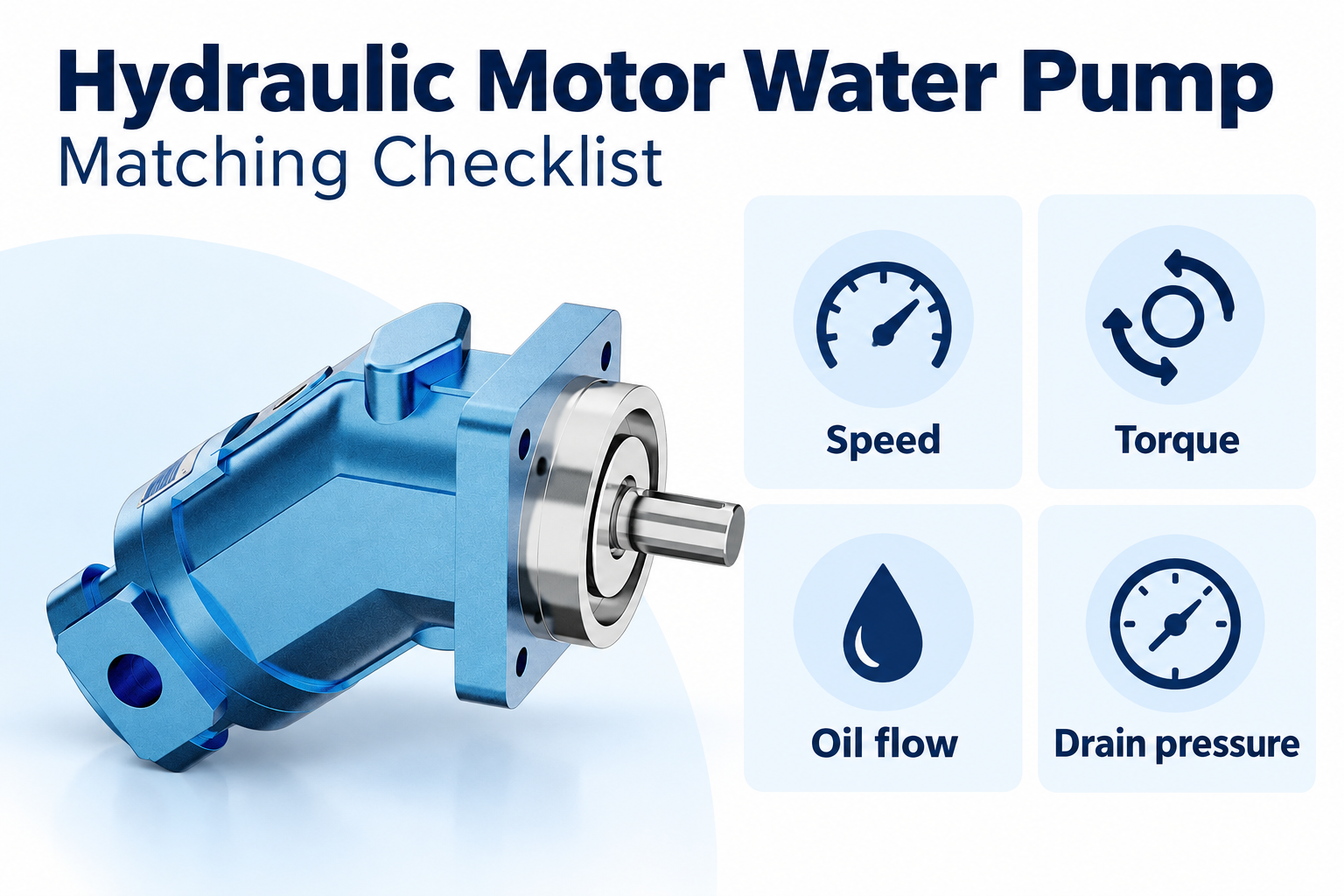
The real catalog motor used in this article’s illustrations shows a product category, not a verified match for the worked example. Confirm the complete ordering code and performance data before using any particular motor. A sensible final selection is a documented combination of water duty, shaft demand, hydraulic capability and installation approval.
Frequently asked questions
Can I size the motor from water discharge pressure alone?
No. You also need water flow, total dynamic head, pump efficiency or absorbed shaft power, and operating speed. Water pressure does not directly specify the oil pressure or motor displacement needed to drive the shaft.
Should I use hydraulic motor overall efficiency in every formula?
No. Mechanical efficiency belongs in the torque relationship and volumetric efficiency in the flow relationship. Overall efficiency relates total input and output power. Use data appropriate to the actual operating point and keep the definitions consistent.
Is the worked example a recommendation for a 15 cm³ motor?
No. It illustrates the calculation using assumed efficiencies and pressure difference. A real selection still needs available motor sizes, performance curves, continuous limits, starting behavior, shaft loads and the water pump’s full demand range.
Why does water flow fall when another hydraulic function operates?
The shared source may not supply the required oil flow and pressure to both functions at once. Check priority controls, supply capability, return losses and actual motor speed under simultaneous operation before changing the water pump.
Does more motor power cure water-pump cavitation?
No. Water inlet conditions must satisfy the water pump’s suction requirements. More speed or power can worsen an unsuitable inlet condition. Check the water supply, suction arrangement and pump documentation before increasing drive output.
Product and related engineering resources
The Fixed Displacement Motor A2FM catalog exterior is used as the real product reference in these explanatory images. It does not establish the approved service method, optional construction, or operating limits for an individual order. Confirm the complete code and its documentation. Related resources: Fixed Displacement Motor A2FM, hydraulic motor range, Hydraulic Motor Power Calculation: Torque, Speed, and Efficiency, Hydraulic Motor Case Drain Line Sizing and Connection Rules.
Sources and limits of this guide
Washington State University distinguishes water-pump brake horsepower from total drive input. The Department of Energy sourcebook supports duty-point, curve, suction and conditional speed-scaling principles. NPTEL explains hydraulic-motor operation. NIOSH supplies hazardous-energy prevention context. All numerical efficiencies and duty values in the worked example are stated assumptions, not product ratings.
- Washington State University Extension: required water-pump horsepower
- U.S. Department of Energy: Improving Pumping System Performance
- NPTEL: Fundamentals of Industrial Oil Hydraulics and Pneumatics
- NIOSH: preventing injuries from hazardous energy
University lesson: operating principles
NPTEL-NOC IITM presents 6.3 – Hydraulic Motors. The lesson supports the hydraulic-motor operation needed when converting water-pump shaft demand into oil flow and pressure requirements used in this discussion; it is not a model-specific performance or installation approval.